Reed switch 3 x contact. What is it? Reed sensors and switches are used in various places
Before starting the story about reed switches, I think it would not be amiss to explain what a reed switch is and “what it is used with.”
Reed switch called sealed magnetically controlled contact. The switch itself can have a variety of configurations. Its simplest and most common configuration is as follows: it consists of a pair of rectangular housings, one of which contains a permanent magnet, and the other a reed switch.
This type of switch is most often used as an opening detector in security systems, having among the security and fire alarm products the name SMK.
This wide application reed switches (sensors) is due to the fact that the penetration of intruders into protected objects, in most cases, occurs through the door by breaking locks or selecting keys. With the help of these detectors, garage doors, doors and windows, as well as various objects are also protected from movement.
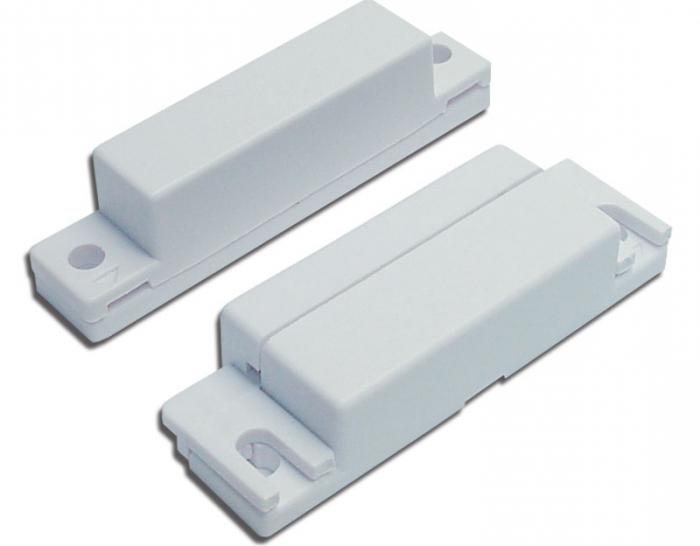
Another type of reed switches are shock-contact type sensors designed to protect glass structures. The reed switch itself looks basically like this. 
Actually, the reed switch consists of a pair (sometimes three, for a switching reed switch) of permalloy plates, which are sealed in a common glass cylinder, inside of which nitrogen is pumped under high pressure.
This allows the devices to operate for up to 12-24 years due to the fact that the materials from which all this is made practically do not age. The device has a very low contact resistance and is capable of operating over a wide range of temperatures and humidity.
Such design features, in addition, imply some limitations in the use of reed switches. Here they are:
- contact compression and, as a consequence, intercontact resistance depend on the strength of the control magnet or the current in the control winding;
- since the gap between the plates is small, the formation of electrical discharges at the moment of closing and opening is facilitated (compared to ordinary contacts);
- due to the closed volume, heat removal is limited and, therefore, the switching ability of the device determines the size of its cylinder;
- if a certain value of the switching current is exceeded, chattering appears and pressing decreases.
There are other restrictions associated with design feature devices.
In general, switches of this type are a large group that are very different in design and application, as well as in the range of capabilities of devices controlled using an external device. magnetic field. These devices have fairly high reliability due to the fact that they are based on the use of a reed switch instead of the main actuator, which is controlled using an external magnetic field.
IN lately Reed switches are used quite widely as switching elements. With their help, low and medium power loads are switched, relays and logical modules, buttons, switches, limit switches, etc. are created.
Their wide distribution is due to the high reliability, speed and stability of contacts. The SMK type switch-detectors themselves may look like this: 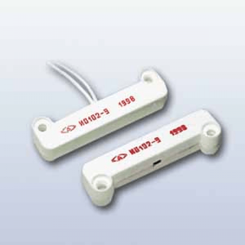
There are, of course, other types of devices, but their basic principle is almost the same. The only differences are appearance and method of management. Some of them are controlled by directly bringing a magnet to it, others, as can be seen from the figure, are controlled by introducing a shunt curtain into the gap between a permanently located magnet and a reed switch.
This is how SMK type sensors can be mounted:
In addition, reed switches and switches can be used in automation and control devices.
At one time, the keyboards of some devices were assembled on them, as well as most of the buttons for control panels of various machines, also made on the basis of reed switches.
The only fairly strong limitation on the use of devices of this type is their small switching current. Therefore, it is best to install them in the control circuit through intermediate relays.
Installation of devices directly into a switched circuit is possible only in those circuits through which currents and voltages of small values flow, for example, in the circuit of security devices.
I hope that the material in my article helped you understand what types of reed switches there are and where they are used.
Write comments, additions to the article, maybe I missed something. Take a look at, I will be glad if you find something else useful on mine. All the best.
A brief history of the creation of reed switches
Switching devices or simply contacts are very widely used in various electrical and radio equipment. In order to improve performance properties, primarily service life and reliability of the connection, they were developed magnetically controlled sealed contacts called reed switches.
The first examples of such contacts appeared back in the 30s of the last century, and the first magnetically controlled contact was invented back in 1922 in St. Petersburg by Professor V. Kovalenkov, for which he was issued a USSR author's certificate No. 466. The design of such a contact is shown in Figure 1.
Such a contact is arranged as follows. Contacts 1 and 2, also made of soft magnetic material, are attached to the core 3 made of soft magnetic material through insulating spacers 5. When current is passed through coil 4, a magnetic field appears in core 3 and magnetizes contacts 1 and 2, which close. The contacts open when the current through the coil stops.
Figure 1. Magnetic-controlled contact of Professor V. Kovalenkov
In fact, this was the very first magnetically controlled contact, only without a sealing shell. A similar contact was first placed in a sealing shell by the American engineer W.B. Ellwood only in 1936. In the seventies of the last century, reed switches reached their maximum development and were widely used in various devices electronic technology.
Currently, reed switches are used less intensively, as they have been “supplanted”. But in some cases, reed switches remained out of competition, which is due to ease of use, galvanic isolation from the power source, and the properties of a “dry contact”, which is why reed switches are still used in various schemes and devices.
In cases where high reliability and durability of the switching element is required reed switches simply irreplaceable. How component Reed switches are included in the designs of various sensors, electromagnetic relays, especially low-current ones, as well as position switches and some other devices.
Types of reed switches
Just like regular contacts, reed switches can be making (1 normally open contact), switching (1 changeover contact) or opening (1 normally open) closed contact). This is a division based on functional characteristics.
Based on structural and technological characteristics, reed switches are divided into two large groups: with dry contacts and with mercury contacts. The first type is called dry reed switches, and the second is called mercury reed switches. Actually, there is nothing special in the operation of dry reed switches, compared to conventional contacts.
In mercury reed switches, inside a sealed glass case, in addition to the contacts, there is also a drop of mercury. The purpose of this mercury droplet is to wet the contacts during actuation to improve the quality of contact by reducing contact resistance, and also to get rid of contact bounce.
Bouncing is the vibration of contacts when closing and opening, which, with a single operation, leads to repeated switching of the transmitted signal, and in addition to a significant increase in the response time.
Imagine that such a bounce will be present when switching the input signal! In the case where such a rattling contact works in conjunction with digital chips, it is necessary to take measures to suppress bounce in the form of RC chains or.
Various contacts, including reed contacts, are also used in, but in them contact bounce is suppressed by software. This also reduces the performance of the system as a whole.
Reed switch design
The design of various types of reed switches is shown in Figure 2.
Figure 2. Reed switch design
All reed switches are sealed glass bottle, inside which is contact group. The contacts are magnetic cores welded into the ends of the cylinder. The outer ends of the cores are designed for connection to an external electrical circuit.
The most widespread reed switch with contact group operating for closure or, as shown in the figure, “open”. Each contact core is made of ferromagnetic elastic wire, which is flattened to a rectangular shape. For the manufacture of cores, permalloy wire with a diameter of 0.5 - 1.3 mm is used, depending on the power of the reed switch and, accordingly, its dimensions.
Directly contacting surfaces are coated with noble metals, gold, palladium, rhodium, silver and alloys based on them. Such a coating not only reduces, but also helps to increase the corrosion resistance of the contact surface.
The internal space of the cylinder is filled with an inert gas (hydrogen, argon, nitrogen or a mixture of them) or simply evacuated, which also helps reduce corrosion of contacts and increase their reliability. During manufacturing, the cores are positioned in such a way that there is a gap between them, by the way, of a certain size.
Rice. 3. Reed switch
Operating principle of a reed switch
In order to trigger the contact group, it is necessary to create a magnetic field of sufficient strength around the reed switch. In this case, it does not matter at all how this field is created, either simply by a permanent magnet or by an electromagnet. Power lines The external magnetic field magnetizes the internal contacts - the reed switch cores, as a result of which they overcome the elastic forces, attract and close the electrical circuit.
The contacts will remain in this state as long as there is a magnetic field of sufficient strength around them: it is enough to turn off the electromagnet or remove an ordinary permanent magnet away, and the contacts will immediately open. The next contact activation will occur when the magnetic field reappears. From all that has been said, we can conclude that the contacts perform three functions at once: elastic elements (springs), a magnetic circuit, and the actual conductive contacts.
A reed switch that operates to open operates somewhat differently. Its magnetic system is designed in such a way that when exposed to a magnetic field, the contacts - the cores - are magnetized in the same way, therefore they repel each other, opening the electrical circuit.
In a switching reed switch, one of the three contacts, as a rule, is normally closed - the closed one is made of non-magnetic metal, and both normally open contacts are made of ferromagnetic, as was said just above. Therefore, when a reed switch is exposed to a magnetic field, the normally open contacts simply close, and the non-magnetic normally closed contact, remaining in its original place, opens.
Note. Normal - open contact, this is which is open in the absence of a control influence, in this case a magnetic field. Respectively normal - closed contact closed in the absence of a magnetic field.
Of course, a magnetic field is always present, for example the Earth's magnetic field. And it seems impossible to say that there is no magnetic field at all. But the Earth’s magnetic field is not enough to trigger the reed switch, so it can be neglected and we can say that there is no magnetic field, in this case external.
Continue reading in the next article.
Continuation of the article:
Boris Aladyshkin
In a wide variety of electrical and electronic circuits, a radio component with the beautiful name “reed switch” is used. What is it and how does it work?
Name and its meaning
The name really sounds poetic, it is worthy of a beautiful flower. But the origin of the word is very prosaic; it stands for “hermetic contact.” It is the absence of air or its replacement that determines the advantages of the device compared to conventional contact groups. The principle of its operation is extremely simple, and is briefly explained by another name for the part: “magnetic controlled electrical connection”. Inside a glass cone small sizes two elastic metal plates are fixed, one of which is equipped with a ferromagnetic pad. Sealing is achieved by a tight fit of the amorphous material of the case at the time of manufacture, in other words, the leads are simply fused on both sides.
Device structure
So, inserted into a glass tube mechanical system, consisting of two springy plates, magnetic material and contact groups deposited or soldered on them. In a normal state, the right and left components can be in galvanic contact, allowing passage electric current(such reed switches are called normally closed), or, on the contrary, can be open (closed reed switch). Then a vacuum is created inside the tube or an inert (chemically passive) gas is pumped into it. This is done to enlarge the detail. When current passes, the contacts heat up and the oxidation process, that is, connection with oxygen, accelerates. If the metal is surrounded by an inert environment, then such a reaction will not occur. Now the tube can be sealed, and the device is ready.

Operation of the device, its advantages and disadvantages
Application
And yet, despite the design fundamental defects, which are almost impossible to completely eliminate, the characteristics of reed switches allow them to be used in many areas of human activity, in which the disadvantages are not so important, and the advantages predominate. For example, in a regular computer keyboard, in which you can combat the so-called “bounce” by including damping filters in the circuit, and then not worry about the cleanliness of the contacts. These devices are also indispensable in alarm systems. There is nothing simpler than installing a sensor, which is based on a reed switch connected to the circuit. The doors are closed - the contact is closed, and when they open, the magnet attached to the jamb moves away, decreases, and the circuit opens, serving as a signal to trigger electronic circuit alerts. Reed switches are also most often used to determine the position of the elevator car. Divers' lighting equipment can also be easily controlled using magnets without the fear of salty seawater flowing into the electric lights through openings in the switching fixtures. In both single-phase and three-phase circuits, reed switches are also present.

Herkotrons
When studying high-voltage circuits, students and specialists sometimes come across the term “reed switch”, while from the context it is clear that in its fundamental design this is the same reed switch. What is it and what is the difference? In characteristics, namely in voltage (up to 100 kV) and current that can flow through the contacts. The ability of the insulation to withstand the possibility of breakdown and the cross-section of the conductor, as well as the contact area, is what distinguishes the reed switch from the reed switch. In all other respects, and most importantly, in the fundamental design, these devices are identical.
I purchased these sensors based on a tip from the comments to one of my previous reviews.
By and large, there is nothing to review here, since the principle of their operation is simple, but one of my friends became interested in what it actually is and how it works - and decided to write this small visual review about this.
Operating principle
Reed switch ( ger cross-linked con tact) is a glass cone, inside of which there are two elastic contact ferromagnetic plates, which, when immersed in a magnetic field, close and a contact is formed, through which current then flows.
The flask is usually filled with an inert gas or contains a vacuum. An example of the work is shown schematically in the animation below, where an ordinary magnet is brought up.
Why do the plates actually close and open due to the presence of a magnetic field? As mentioned above, the plates themselves are ferromagnetic, i.e. they actively attract a magnet to themselves and at the same time they themselves are actively attracted by a magnet. Regular iron has similar properties. A magnet has two polarities - north and south, and the magnetic lines always go from the north pole to the south. When a magnet is brought to the reed switch, magnetic lines will also pass through these elastic plates. In this case, in the figure, the north pole of the magnet is located on the left, the south pole on the right. Accordingly, the edge of the upper plate becomes south polarity, and the edge of the lower plate becomes north polarity - as a result, the plates are closed. When the magnet moves away, the plates open due to their elasticity. If the magnet is not positioned correctly in relation to these plates, then the magnetic lines will pass through them unevenly, and the contacts will not be able to close. 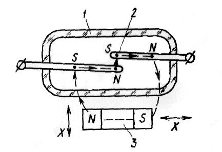
There are three main types of reed sensors on sale:
1)
Normally open (observable), which are normally open, but when immersed in a magnetic field, the circuit closes.
2)
Normally closed is the opposite principle: in the normal state the contacts are closed, but when immersed in a magnetic field the contacts open.
3)
Reed switches, unlike the first two, already have 3 outputs and 3 plates inside, respectively. In a quiet state, one pair of contacts is closed; when immersed in a magnetic field, the other pair is closed.
Reed switches can also be designed for switching high current or mercury, where the contact points of the plates are moistened with a drop of mercury to suppress contact bounce. The main application of reed switches is security and automation systems, as the simplest example - automatic start any action when opening a door or window, for example sending an alarm. Reed relays are made on the basis of reed switches - in high-voltage installations these are used to protect against current overloads, in this case the reed switch is placed in a coil.
Appearance. Dimensions
I took 10 normally open (open) ones.
Glass capsule with a slightly greenish tint. 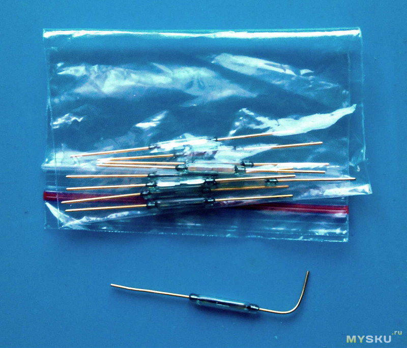
Dimensions correspond to 2x14mm 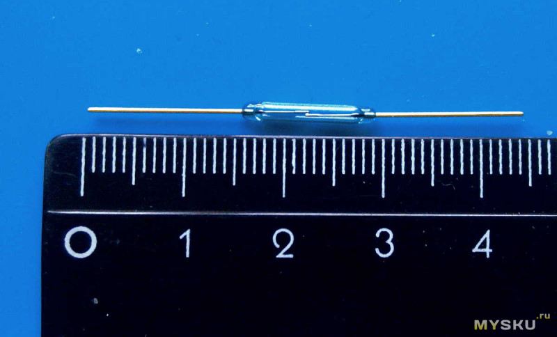

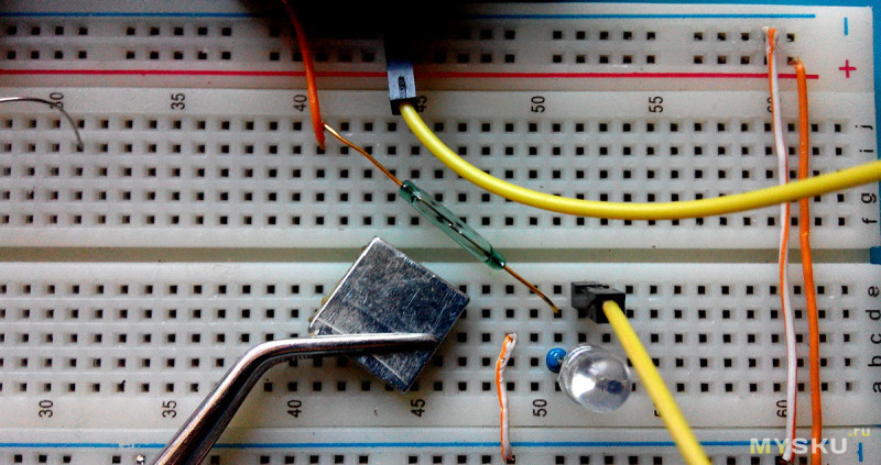
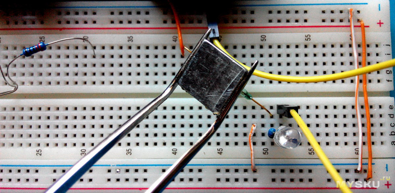
Assembled on a breadboard simple circuit with an LED, in the gap of which I placed a reed switch in order to check its operation by bringing a flat neodymium magnet to it, and since the magnetic fields have different poles, the contacts in the reed switch close stably only if the magnet is directed at it end-to-end and across. 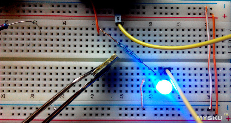
In other positions of the magnet, the contacts in the reed switch will not be closed: 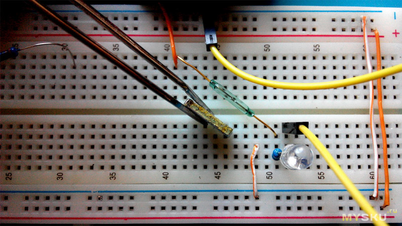
An example with magnets from a motor: turning one side - the contacts close, the other side - no reaction. Therefore, this point is worth taking into account.
How the state of the plates changes - enlarged under a digital microscope
On top of that, it would be nice to show a simple visual test of the operation of this sensor with performing some action when opening and closing a room door, for example, turning on table lamp by means of .
First you need to pack the reed switch itself. 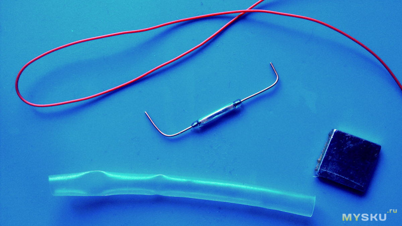
A piece of heat shrink is put on and pressed with hot air. 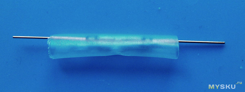
One terminal needs to be bent. But then the first pancake was waiting for me, lumpy - having bent the lead almost at the very base of the cone - the glass broke and the reed switch became unusable: ![]()
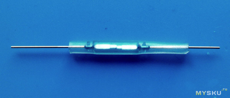
To prevent this from happening, you need to pinch the terminal 1-2mm from the base of the capsule with tweezers and only then bend it: 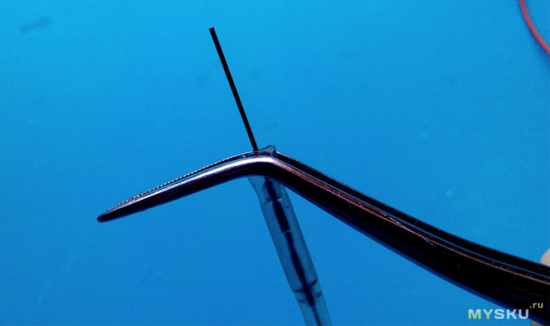
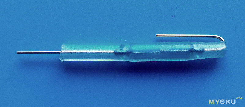
The second lead was slightly shortened, along with heat shrink 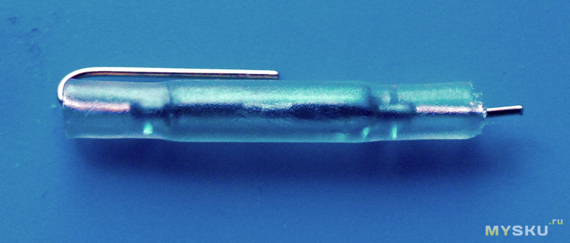
I solder the wire to both terminals of the wire 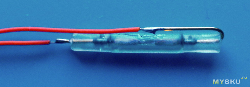
Now this whole thing needs to be secured somehow. Therefore, I chopped the glue gun rod into small slices: 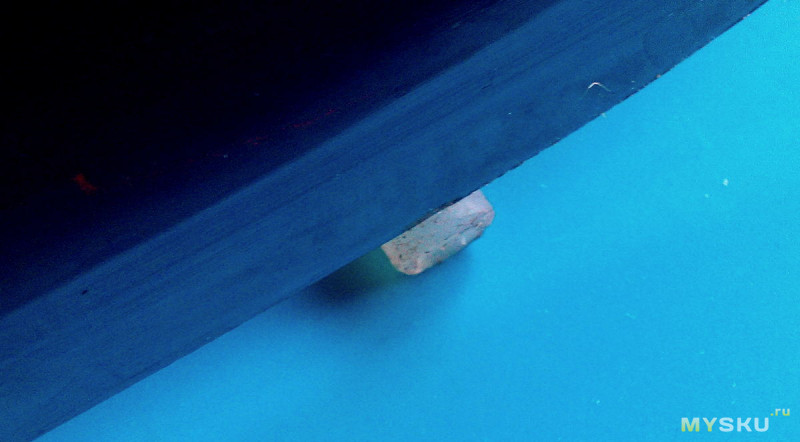
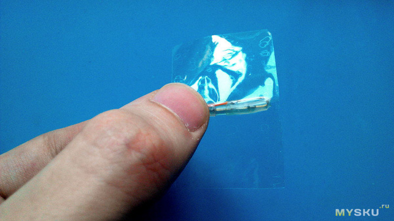
I put more heat shrink on the top of the reed switch and stuffed some hot melt glue inside at the base: 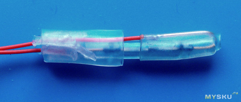
Blown hot air 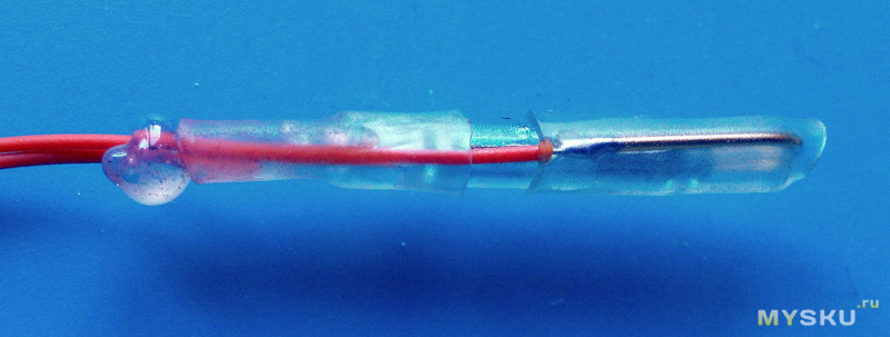
Removed excess glue 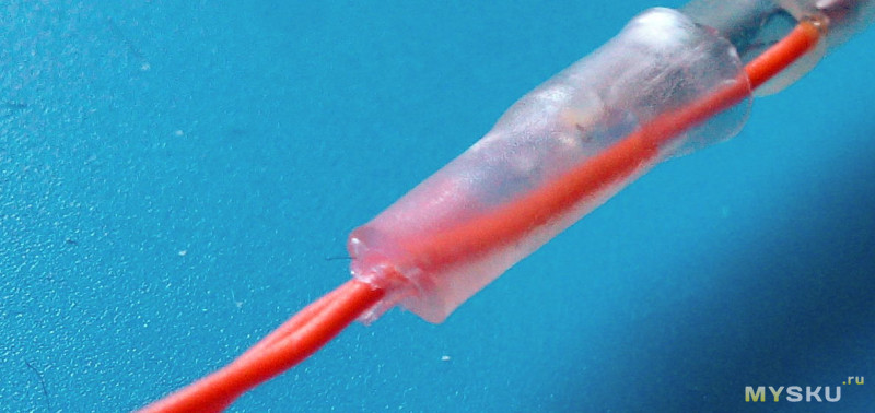
The matter remains small. Attach the magnet to the door and the reed switch to the wall opposite the magnet. For a demonstration test, ordinary tape would also work here, fortunately you can quickly remove everything back and forth. 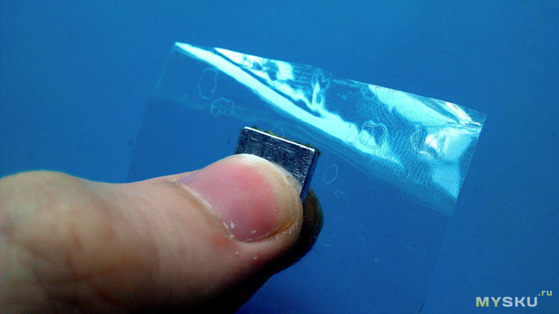
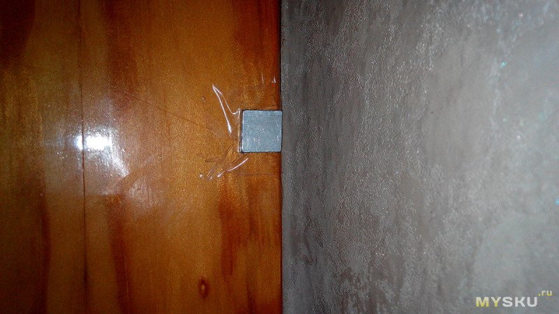
The magnet and the reed switch are located across each other 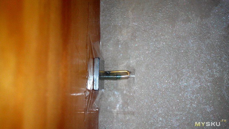
The electronic-software part is simple: the Pro Mini board is configured for an external interrupt, where the interrupt output through this same reed switch is connected to the board's power supply, and while the door is closed and there is a magnet near the reed switch, the circuit is closed, the controller is asleep, and the relays that control the lamp are turned off. As soon as the door opens and the magnet is moved to the side, the reed switch opens, an external interruption occurs, which sends an impulse to the relay and the lamp turns on.
There can be many applications in DIY projects, especially with simple and cheap Attiny13 controllers or, if the project is very simple, with transistors. Due to its small size, the reed switch can be cleverly hidden from prying eyes. I will use them in new version energy-efficient GSM alarm system, although for its full assembly you need to wait for a few more components. Among the disadvantages, I note the fragility of the capsule and vulnerability to other magnetic fields. Regarding reliability, they write that they have a fairly large closing-opening cycle due to the tightness inside the capsule. In general, we'll see.
I'm planning to buy +46 Add to favorites I liked the review +78 +137Contacts, or switching devices as they are also called, are used in electronic and radio engineering. Reed switches have been developed to improve the quality of operation: service life and, of course, reliability. In this article we will look at technical specifications reed switches, operating principle and scope.
What is it?
Today, reed switches are practically not used, since Hall sensors appeared. But still, in some cases, these products are irreplaceable. They are easy to use, which is why they are also used in various types circuits or devices.
If you need reliability and durability, then this part is irreplaceable. Where is the switch used? It can be included in the design of a sensor, electronic relays and other devices.
Reed switches, like other devices or their parts, are divided into different types.
By function:
- short circuit;
- switching;
- opening.
Design and technical features:
- Dry contact (without any secrets, it works according to the principle described below).
- Mercury contact (in a glass case, mercury drops are added to the contact, which wet them when the reed switch is activated, which improves the quality of the contact. This also avoids contact chatter (vibration), which increases the response time.
Based on this, it is better to use a mercury contact, but this is not always the case.
Design features
The design of the reed switch is a sealed glass container, inside of which there are contacts. These contacts are magnet cores that are welded to the end sides of the bulb. The outer parts of these cores are connected to the electrical network. The diagram below shows the design of the products:  Where:
- Glass flask.
- Switching contact.
- Fixed contact.
The most common are reed sensors for short circuit. Contacts made of rectangular ferromagnetic wire. Depending on the power and size of the reed switch, the cores are made of permalloy wire. The coating can also be replaced with other metals (gold, silver, rhodium and others).
An inert gas is introduced into the flask or evacuated, which prevents the development of corrosion in the reed switch. When manufacturing a part, it is also taken into account that there is a gap of a certain size between the cores.
How does a reed switch sensor work?
The contact group will come into action only if there is a certain magnetic field voltage around the reed switch, which is created in any way, be it constant or electromagnetic. The principle of operation is that the cores inside the flask are magnetized, attracted to one another and thus complete the circuit. All this will be in effect until the magnetic field disappears. Further operations also depend on the presence of a magnetic field around the reed switch.
The principle of operation of a magnetic opening sensor works a little differently. In the presence of a magnetic field, the contacts are magnetized with the same name and repel each other, which opens the circuit.
Switching reed switch with a magnetic field: closes the open contacts, and the non-magnetic contact remains as it was before.
You can clearly see how reed switches work in the video below:
The breakdown voltage of devices can increase up to 5 kV. The sensor is activated in 0.5-2 ms, and turned off in 0.1-0.7 ms, and this is significantly less than, for example, the operation of an electromagnetic relay.
Purpose and scope
Reed switches are still used today in:
- keyboards and synthesizers;
- safety and automation equipment;
- diving equipment;
- equipment for testing and taking measurements;
- equipment in medical institutions and communication devices.
For example, in security systems, a reed switch is used as a relay. The devices are also used in security sensors. This is what it looks like: a reed switch plus a magnet. If we consider reed relay, then it consists of: a reed switch and a wire winding. The advantages of such a relay are:
- small size and simplicity of design;
- is not affected by moisture and burns of contacts;
- no moving elements.
Such details can be used in many ways and places. But one significant drawback is low impact resistance, and this is important for various types of systems, sensors, etc.
Pros and cons of the device
The use of reed sensors has produced both positive and negative aspects:
- design that allows for reduction in size;
- fast operation and shutdown;
- cores are completely sealed;
- electrical strength between contacts;
- long service time (except for blows);
- The reed switch operates in any weather conditions from -60 to +120 degrees.
- low impact resistance;
- perception of external magnetic fields;
- low power when switching the circuit;
- random opening at high current;
- Sometimes shorting and opening may occur randomly.
If you need to use reed switches, then consider the following application nuances:
- Ultrasound must be avoided as it can affect and change the electrical characteristics.
- When installing, be aware that the magnetic field may change the characteristics of the switch.
- Do not hit or drop reed switches, as Due to the inert gas, which becomes loose upon impact, the cylinder may burst, which will disable the device.
- You should follow the manufacturer's recommendations when soldering.
Specifications
All technical characteristics of the main types of reed switches are given in the table below:

The marking of reed switches depends on the area in which they operate. Each of the existing abbreviations means something (for example, KEM - switching of electrical mechanisms, A - work in any climatic conditions, B – work only indoors). When choosing, you need to take these nuances into account.
You can find switches in electrical stores, radio markets, or order them online. If you need a reed switch for a car, you can purchase it at a car service center. It is also possible to make a reed switch yourself, but this requires expensive equipment.
So we looked at the technical characteristics of reed switches, as well as their operating principle and scope of application. We hope you now understand what these switches are and what they are used for.
Like( 0 ) I don't like it( 0 )