What is current in physics. Big encyclopedia of oil and gas
Send your good work in the knowledge base is simple. Use the form below
Students, graduate students, young scientists who use the knowledge base in their studies and work will be very grateful to you.
Posted on http://www.allbest.ru/
What is called an electric current
Introduction
Electric current - the ordered movement of charged particles under the influence of forces electric field or outside forces.
The direction of motion of positively charged particles is chosen as the direction of the current.
An electric current is called constant if the current strength and its direction do not change over time.
1. Conditions for the existence of a constant electric current
For the existence of a constant electric current, the presence of free charged particles and the presence of a current source are necessary. in which the transformation of any type of energy into the energy of an electric field is carried out.
A current source is a device that converts some type of energy into the energy of an electric field. In a current source for charged particles in closed circuit outside forces are acting. The reasons for the occurrence of external forces in different current sources are different. For example, in batteries and galvanic cells, external forces arise due to the course of chemical reactions, in generators of power plants they arise when a conductor moves in a magnetic field, in photocells - when light acts on electrons in metals and semiconductors.
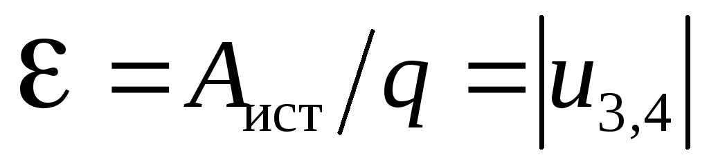
The electromotive force of a current source is the ratio of the work of external forces to the amount of positive charge transferred from the negative pole of the current source to the positive one.
Current strength - scalar physical quantity, equal to the ratio of the charge that has passed through the conductor to the time during which this charge has passed.
where I is the current strength, q is the amount of charge (amount of electricity), t is the charge transit time.
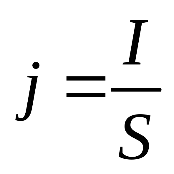
Current density is a vector physical quantity equal to the ratio of the current strength to the cross-sectional area of \u200b\u200bthe conductor.
where j is the current density, S is the cross-sectional area of \u200b\u200bthe conductor.
The direction of the current density vector coincides with the direction of motion of positively charged particles.
Voltage is a scalar physical quantity equal to the ratio of the total work of the Coulomb and external forces during the movement of a positive charge on the site to the value of this charge.
where A is the total work of external and Coulomb forces, q is the electric charge.
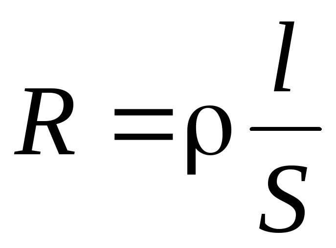
Electrical resistance is a physical quantity that characterizes the electrical properties of a section of a circuit.
where c is the resistivity of the conductor,
l is the length of the conductor section,
S is the cross-sectional area of \u200b\u200bthe conductor.
Conductivity is the reciprocal of resistance
where G is the conductivity.
2. Ohm's laws
Ohm's law for a homogeneous section of a chain.
The current strength in a homogeneous section of the circuit is directly proportional to the voltage at a constant resistance of the section and inversely proportional to the resistance of the section at a constant voltage.
where U is the voltage on the site,
R is the resistance of the section.
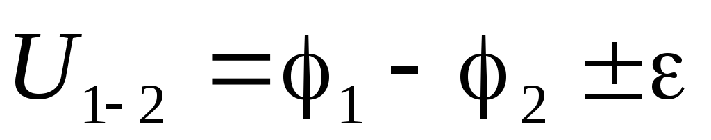
Ohm's law for an arbitrary section of a circuit containing a source direct current.
c1 - c2 + e \u003d U
voltage at a given section of the circuit, R - electrical resistance a given section of the chain.
Ohm's law for complete chain.
The current in the complete circuit is equal to the ratio electromotive force source to the sum of the resistances of the external and internal sections of the circuit.
where R is the electrical resistance of the outer section of the circuit, r is the electrical resistance of the inner section of the circuit.
3. Short circuit
It follows from Ohm's law for a complete circuit that the current in a circuit with a given current source depends only on the resistance of the external circuit R.
If a conductor with resistance R is connected to the poles of the current source<< r, то тогда только ЭДС источника тока и его сопротивление будут определять значение силы тока в цепи. Такое значение силы тока будет являться предельным для данного источника тока и называется током короткого замыкания.
4. Serial and parallel connection of conductors
The electrical circuit includes a current source and conductors (consumers, resistors, etc.), which can be connected in series or in parallel.
With a serial connection, the end of the previous wire is connected to the beginning of the next.
In all series-connected conductors, the current strength is the same:
The resistance of the entire section is equal to the sum of the resistances of all individual conductors:
The voltage drop across the entire section is equal to the sum of the voltage drops on all individual conductors:
The voltages on the series-connected conductors are proportional to their resistances.
In a parallel connection, the conductors are connected to the same points in the circuit.
The current in the unbranched part of the circuit is equal to the sum of the currents flowing in each conductor:
The reciprocal of the resistance of the branched section is equal to the sum of the reciprocals of the reciprocal resistances of each individual conductor:
The voltage drop across all conductors is the same:
The currents in the conductors are inversely proportional to their resistances
Mixed connection is a combination of parallel and serial connections.
5. Kirchhoff rules
Kirchhoff rules are used to calculate branched chains containing heterogeneous sections. Calculation of complex circuits consists in finding currents in different parts of the circuits.
A node is a point in a branched circuit where more than two conductors converge.
1 Kirchhoff's rule: the algebraic sum of the forces of currents converging at the node is equal to zero;
where n is the number of conductors converging at the node, Ii is the current in the conductor.
currents entering the node are considered positive, currents leaving the node - negative.
2 Kirchhoff's rule: in any arbitrarily chosen closed loop of a branched circuit, the algebraic sum of the products of the forces of currents and resistances of each of the sections of this loop is equal to the algebraic sum of the EMF in the loop.
To take into account the signs of the currents and EMF forces, a certain direction of the loop bypass (clockwise or counterclockwise) is selected.
Currents are considered positive, the direction of which coincides with the direction of bypassing the loop, negative currents are considered to be in the opposite direction. EMF of sources of electrical energy is considered positive if they create currents, the direction of which coincides with the direction of bypassing the circuit, otherwise - negative.
6. The procedure for calculating a complex DC circuit
The direction of currents in all sections of the circuit is arbitrarily chosen.
The first Kirchhoff rule is written for an (m-1) node, where m is the number of nodes in the chain.
Arbitrary closed contours are selected, and after choosing the direction of the bypass, the second Kirchhoff rule is recorded.
The system of composed equations must be solvable: the number of equations must correspond to the number of unknowns.
Shunts and additional resistances.
Shunt is a resistance connected in parallel to an ammeter (galvanometer) to expand its scale when measuring current.
If the ammeter is designed for current I0, and with the help of it it is necessary to measure a current that is n times the permissible value, then the resistance of the connected shunt must satisfy the following condition:
Additional resistance - a resistance connected in series with a voltmeter (galvanometer) to expand its scale when measuring voltage.
If the voltmeter is designed for voltage U0, and with the help of it it is necessary to measure a voltage that is n times greater than the permissible value, then the additional resistance must satisfy the following condition:
7. Permanent electricity
Direct current (DC - Direct Current) - an electric current that does not change its magnitude and direction over time.
In reality, direct current cannot keep the value constant. For example, at the output of rectifiers, there is always an alternating ripple component. When using galvanic cells, batteries or accumulators, the current value will decrease as the energy is consumed, which is important under heavy loads.
Direct current exists conditionally in those cases where changes in its constant value can be neglected.
Constant component of current and voltage. DC
If we consider the shape of the current in the load at the output of rectifiers or converters, you can see ripples - changes in the magnitude of the current that exist as a result of the limited capabilities of the filter elements of the rectifier. In some cases, the ripple value can reach sufficiently large values \u200b\u200bthat cannot be ignored in calculations, for example, in rectifiers without the use of capacitors. This current is commonly referred to as pulsating or pulsed. In these cases, the DC and AC components should be considered.
DC component DC - a value equal to the average current value over the period.
AVG stands for Avguste - Average.
The alternating component AC is a periodic change in the value of the current, a decrease and an increase relative to the average value.
It should be borne in mind in calculations that the value of the ripple current will not be equal to the average value, but the square root of the sum of the squares of two quantities - the constant component (DC) and the rms value of the alternating component (AC), which is present in this current, has a certain power and is added to DC power.
The above definitions, as well as the terms AC and DC, can be used equally for both current and voltage.
The difference between DC and AC
According to associative preferences in the technical literature, the pulse current is often called constant, since it has one constant direction. In this case, it is necessary to clarify that we mean direct current with an alternating component. And sometimes it is called a variable, for the reason that it periodically changes the value. Alternating current with a constant component. Usually they take as a basis the component that is larger in size or that is most significant in the context.
It should be remembered that a constant current or voltage characterizes, in addition to the direction, the main criterion - its constant value, which serves as the basis of physical laws and is decisive in the calculation formulas of electrical circuits. The DC component DC, as an average value, is only one of the parameters of AC.
For alternating current (voltage), in most cases, the criterion is important - the absence of a constant component, when the average value is zero. This is the current that flows in capacitors, power transformers, power lines. This is the voltage across the windings of transformers and in the household electrical network. In such cases, the DC component can only exist in the form of losses caused by the non-linear nature of the loads.
8. Constant current and voltage parameters
It should be noted right away that the outdated term "current strength" in modern domestic technical literature is already used infrequently and is recognized as incorrect. Electric current is characterized not by force, but by the speed and intensity of movement of charged particles. Namely, the amount of charge that has passed per unit time through the cross section of the conductor. The main parameter for direct current is the current value.
The unit of current measurement is Ampere. The magnitude of the current is 1 Ampere - moving the charge 1 Coulomb in 1 second.
The unit of voltage is Volt. The voltage value of 1 Volt is the potential difference between two points of the electric field, required to do work 1 Joule when passing a charge of 1 Coulomb.
For rectifiers and converters, the following parameters are often important for DC voltage or current:
The voltage (current) ripple is a value equal to the difference between the maximum and minimum values. Ripple factor is a value equal to the ratio of the rms value of the AC voltage or current component to its DC component.
Electrical circuits and their elements
An electrical circuit is a collection of devices and objects that form a path for an electric current, the electromagnetic processes in which can be described using the concepts of electromotive force, current and voltage. In a direct current electric circuit, both direct currents and currents can act, the direction of which remains constant, and the value changes arbitrarily in time or according to some law.
The electrical circuit consists of individual devices or elements, which, according to their purpose, can be divided into 3 groups. The first group consists of elements intended for generating electricity (power sources). The second group includes elements that convert electricity into other types of energy (mechanical, thermal, light, chemical, etc.). These elements are called receivers of electrical energy (electrical receivers). The third group includes elements designed to transmit electricity from a power source to an electrical receiver (wires, devices that ensure the level and quality of voltage, etc.).
DC power sources are galvanic cells, electric accumulators, electromechanical generators, thermoelectric generators, photocells, etc. All power sources have an internal resistance, the value of which is small in comparison with the resistance of other elements of the electric circuit.
DC electrical receivers are electric motors that convert electrical energy into mechanical, heating and lighting devices, etc. All electrical receivers are characterized by electrical parameters, among which the most basic ones can be called - voltage and power. For normal operation of the electrical receiver, it is necessary to maintain the rated voltage at its clamps (terminals). For DC receivers, it is 27, 110, 220, 440 V, as well as 6, 12, 24, 36 V.
A graphic representation of an electrical circuit, containing the symbols of its elements and showing the connections of these elements, is called an electrical circuit diagram. Table 2 shows the symbols used in the depiction of electrical circuits.
Symbols in wiring diagrams
|
Galvanic or rechargeable cell or |
Closing contacts with time delay |
|
|
Battery of elements |
when closing |
|
|
Electromechanical DC generator |
on opening |
|
|
Switch, make contact |
when closing and opening |
|
|
Automatic switch |
Fuse fuse |
|
|
Contactor and electrical relay contacts: |
Contactor, magnetic starter and relay coil |
|
|
closing |
Incandescent lamp |
|
|
disconnecting |
||
|
switching |
||
|
Discharge lighting lamp |
Fixed capacitor |
|
|
Ammeter and voltmeter |
Inductor |
|
|
Constant resistor |
Semiconductor diode |
|
|
Variable resistor |
A section of an electrical circuit along which the same current flows is called a branch. The junction of the branches of an electrical circuit is called a node. On wiring diagrams, the node is indicated by a dot. Any closed path that passes through several branches is called an electrical circuit. The simplest electrical circuit has a single circuit, complex electrical circuits - several circuits.
The elements of an electrical circuit are various electrical devices that can operate in different modes. The modes of operation of both individual elements and the entire electrical circuit are characterized by the values \u200b\u200bof current and voltage. Since the current and voltage in the general case can take any values, then there can be an infinite number of modes.
Idle mode is a mode in which there is no current in the circuit. This situation can occur when the circuit is broken. The nominal mode happens when the power supply or any other element of the circuit operates at the values \u200b\u200bof current, voltage and power specified in the passport of this electrical device. These values \u200b\u200bcorrespond to the most optimal operating conditions of the device in terms of efficiency, reliability, durability, etc.
Short-circuit mode is a mode where the resistance of the receiver is zero, which corresponds to the connection of the positive and negative terminals of the power supply with zero resistance. The short-circuit current can reach high values, many times higher than the rated current. Therefore, the short circuit mode for most electrical installations is emergency.
The matched mode of the power supply and the external circuit occurs when the resistance of the external circuit is equal to the internal resistance. In this case, the current in the circuit is 2 times less than the short-circuit current.
The most common and simplest types of connections in an electrical circuit are series and parallel connections.
9. Series connection of circuit elements
In this case, all elements are connected to the circuit one after the other. Serial connection does not provide an opportunity to obtain a branched chain - it will be unbranched. In fig. 1 shows an example of a series connection of elements in a circuit.
Figure: 1. Series connection of two resistors in the circuit: 1 - the first resistor; 2 - the second resistor
In our example, two resistors are taken. Resistors 1 and 2 have resistances R1 and R2. Since the electric charge in this case does not accumulate (direct current), then for any cross-section of the conductor, the same charge passes over a certain time interval. It follows from this that the current strength in both resistors is equal: I \u003d I1 \u003d I2
But the voltage at their ends is summed up:
According to Ohm's law, for the entire section of the circuit and for each resistor separately, the total resistance of the circuit will be:
In the case of a series connection of conductors, voltage and resistance can be expressed by the ratio:
Parallel connection of conductors
When two conductors are connected in parallel, the circuit has two branches. Branching points of conductors are called nodes. In them, the electric charge does not accumulate, that is, the electric charge entering the node over a certain period of time is equal to the charge leaving the node during the same time. It follows that:
where I is the current in an unbranched circuit.
When the conductors are connected in parallel, the voltage across them will be the same. Parallel connection of conductors is shown in fig. 2.
Figure: 2. Parallel connection of two conductors: points a and b - nodes
Let's designate the resistances of the parallel-connected two conductors R1 and R2. Using Ohm's law for sections of an electrical circuit with given resistances, it can be revealed that the inverse value of the total resistance of the section ab is equal to the sum of the values \u200b\u200binverse to the resistances of individual conductors, i.e.
1 / R \u003d 1 / R1 + 1 / R2
It follows from this:
R \u003d R1R2 / (R1 + R2)
This formula is only valid for determining the total resistance of two conductors connected in parallel. The reciprocal of resistance is called conductivity. When the conductors are connected in parallel, their resistance and current strength are related by the ratio:
10. Capacitor connections
Capacitors also have two types of connection: series and parallel.
Serial connection. In this case, the plate of one capacitor, charged negatively, is connected to the plate of another capacitor, charged positively.
In fig. 3 shows an example of a series connection of capacitors.
Figure: 3. Series connection of two capacitors
With this type of connection, the following rule applies: the reciprocal of the capacitance of the capacitor bank when connected in series is equal to the sum of the reciprocal of the capacitances of the individual capacitors. Therefore:
1 / С \u003d 1 / С1 + 1 / С2 + 1 / С3 + ...
With this type of connection, the capacitance of the capacitor bank is less than that of any of the capacitors.
Parallel connection. When capacitors are connected in parallel, positively charged plates are connected to positively charged ones, and negatively charged ones to negative ones (Fig. 4).
Figure: 4. Parallel connection of two capacitors
In this case, the capacity of the capacitor bank will be equal to the sum of the electrical capacitances of the capacitors:
C \u003d C1 + C2 + C3 + ...
11. Power supply connections
Current sources can also be connected to a battery in two ways: parallel and serial. How to connect current sources in the first way is shown in Fig. five.
Figure: 5. Parallel connection of current sources
With the parallel method of connecting the current sources, all positive and all negative poles are connected together. The voltage on an open battery will be equal to the voltage on each individual source, i.e., with a parallel connection method, the EMF of the battery is equal to the EMF of one source. The resistance of the battery when the sources are connected in parallel will be less than the resistance of one element, because in this case their conductivities are summed up.
When the current sources are connected in series (Fig. 6), two adjacent sources are connected by opposite poles.
The potential difference between the positive pole of the last source and the negative pole of the first will be equal to the sum of the potential differences between the poles of each source. It follows from this that with a series connection, the EMF of the battery is equal to the sum of the EMF of the sources included in the battery. The total resistance of the battery when the sources are connected in series is equal to the sum of the internal resistances of the individual elements.
Figure: 6. Series connection of current sources
12. Calculation of electrical circuits
The basis for calculating electrical circuits is to determine the strength of currents in individual sections at a given voltage and a previously known resistance of individual conductors. For example, let's take an electrical circuit, such as shown in fig. 7.
Figure: 7. Simple electrical circuit
Let's say we know the total voltage at the ends of the circuit. Also known are the resistances R1, R2 ... R6 connected to the chain of resistors R1, R2, R3, R4, R5, R6 (the resistance of the ammeter is not taken into account). Calculate the strength of the currents I1, I2, ... I6.
First of all, you need to clarify how many consecutive sections a given chain has. Based on the proposed scheme, it can be seen that there are three such sections, with the second and third containing branches. Let's assume that the resistances of these sections are R1, R ", R". This means that all the resistance of the circuit can be expressed as the sum of the resistances of the sections:
R \u003d R1 + R "+ R"
where R "is the total resistance of the parallel-connected resistors R2, R3 and R4, and R" is the total resistance of the parallel-connected resistors R5 and R6. Applying the law of parallel connection, you can calculate the resistances R "and R":
1 / R "\u003d 1 / R2 + 1 / R3 + 1 / R4 and 1 / R" \u003d 1 / R5 + 1 / R6
In order to determine the current strength in an unbranched circuit using Ohm's law, you need to know the total resistance of the circuit at a given voltage. To do this, use the formula:
From the above, we can deduce that I \u003d I1.
But to determine the current in individual branches, you must first calculate the voltage in individual sections of the series circuits. Again, using Ohm's law, you can write:
U1 \u003d IR1; U2 \u003d IR "; U3 \u003d IR"
Now, knowing the voltage in individual sections, you can determine the current strength in individual branches:
I2 \u003d U2 / R2; I3 \u003d U2 / R3; I4 \u003d U2 / R4; I5 \u003d U3 / R5; I6 \u003d U3 / R6
There are times when it is necessary to calculate the resistances of individual sections of the circuit using already known voltages, current strength and resistance of other sections, and also determine the required voltage according to the given resistances and current strength. The method for calculating electrical circuits is always the same and is based on Ohm's law.
An electrical circuit is a collection of devices connected in a specific way that provide a path for an electric current to flow.
The elements of an electrical circuit are: current source, load and conductors. The simplest electrical circuit is shown in Figure 1.
Figure 1. The simplest electrical circuit.
The electrical circuit may include other elements, such as switching devices, protection devices.
As you know, for the occurrence of current, it is necessary to connect two points, one of which has an excess of electrons in comparison with the other. In other words, it is necessary to create a potential difference between these two points. A current source is used to create a potential difference in the circuit. The source of current in an electrical circuit can be devices such as generators, batteries, chemical elements, etc.
Any consumer of electrical energy is considered a load in an electrical circuit. The load resists the electric current and the value of the current depends on the value of the load resistance. The current from the current source to the load flows through the conductors. They try to use materials with the lowest resistance (copper, silver, gold) as conductors.
It is important that for the current to flow in the circuit, the circuit must be closed!
Types of electrical circuits
In electrical engineering, by the type of connection of the elements of an electrical circuit, the following electrical circuits exist:
sequential electrical circuit;
parallel electrical circuit;
series-parallel electrical circuit.
Serial electrical circuit.
In a sequential electrical circuit (Figure 2.), all elements of the circuit are in series with each other, that is, the end of the first with the beginning of the second, the end of the second with the beginning of the first, etc.
Figure 2. Serial electrical circuit.
With such a connection of the circuit elements, the current has only one path of flow from the current source to the load, while the total circuit current Itotal will be equal to the current through each circuit element:
Itot \u003d I1 \u003d I2 \u003d I3
The voltage drop along the entire circuit, that is, in the section A-B (Ua-b), will be equal to the voltage E applied to this section and is equal to the sum of the voltage drops in all sections of the circuit (resistors):
E \u003d Ua-b \u003d U1 + U2 + U3
13. Parallel electrical circuit
In a parallel electrical circuit (Figure 3.), all elements are connected in such a way that their beginning is connected to one common point, and the ends to another.
Figure 3. Parallel electrical circuit.
In this case, the current has several paths of flow from the source to the loads, and the total current of the circuit Itotal will be equal to the sum of the currents of the parallel branches:
Itot \u003d I1 + I2 + I3
14. Series-parallel electrical circuit
electric current voltage ohm
A series-parallel electrical circuit is a combination of a series and a parallel circuit, that is, its elements are connected both in series and in parallel (Figure 4).
Figure 4. Series-parallel electrical circuit.
Posted on Allbest.ru
...Similar documents
Conditions necessary for the existence of an electric current. Advantages and disadvantages of parallel connection of conductors. The unit of current strength. The work of an electric current in a closed electric circuit. Ohm's law for a section of a chain. Chemical action of the current.
presentation added on 02/07/2015
Electric circuit and electric current concept. What is electrical conductivity and resistance, definition of unit electric charge... The main elements of the circuit, parallel and serial connections. Instruments for measuring current and voltage.
presentation added 03/22/2011
Calculation of linear DC electric circuits, determination of currents in all branches of the methods of loop currents, superposition, coagulation. Non-linear DC electric circuits. Analysis of the electrical state of linear AC circuits.
term paper added on 05/10/2013
The concept of electric current, the choice of its direction, action and strength. The movement of particles in a conductor, its properties. Electrical circuits and types of connections. Joule-Lenz's law on the amount of heat released by a conductor, Ohm's law on the strength of the current in the circuit section.
presentation added on 05/15/2009
Study of the main features of electromagnetic processes in AC circuits. Characteristics of sinusoidal electric single-phase circuits. Calculation of a complex DC electric circuit. Drawing up a complete system of Kirchhoff equations.
abstract, added 07/27/2013
Basic quantities of electric current and principles of its measurement: Ohm's law, Joule-Lenz's law, electromagnetic induction. Electrical circuits and forms of their construction: series and parallel connection in a circuit, an inductor and a capacitor.
abstract, added 03/23/2012
Basic laws and methods of analysis of linear DC circuits. Linear electric circuits of sinusoidal current. Steady-state mode of a linear electric circuit powered from sources of sinusoidal EMF and currents. Three-phase system with load.
term paper added on 04/15/2010
Basic concepts and special sections of electrodynamics. Conditions for the existence of an electric current, the calculation of its work and power. Ohm's law for direct and alternating current. Current-voltage characteristic of metals, electrolytes, gases and a vacuum diode.
presentation added on 11/30/2013
Causes of electric current. Ohm's law for a non-uniform section of a chain. Ohm's law in differential form. Work and power. Joule – Lenz law. Current density, continuity equation. Current source efficiency. Distribution of tension and potential.
presentation added on 02/13/2016
Characterization of the electric field as a type of matter. Study of the features of conductors, semiconductors and dielectrics. The movement of current in an electrical circuit. Study of Ohm's, Joule-Lenz's and Kirchhoff's laws. Insulation materials. Electromotive force.
Page 2
Such an ordered movement of electric charges is an electric current.
Such an ordered movement of electric charges in a conductive medium, which occurs under the action of the forces of an electric field, is called an electric current.
If the ordered movement of electric charges occurs along a conductor or dielectric, then in the forward direction, then in the opposite direction and, moreover, with a varying average speed, then such an ordered movement of free or bound electric charges creates a current called alternating. Therefore, an alternating current is an electric current that varies in magnitude and direction.
Any ordered movement of charged particles (or bodies) is called an electric current. The direction of movement of positive charges is conventionally taken as the direction of the current.
This ordered movement of electric charges along a conductor under the action of an external electric field is called an electric current.
It is convenient to express the rate of ordered motion of carriers in terms of the current density (formula (55.1)) u jlne, where e is the magnitude of the charge of the carrier and n is the concentration.
The phenomenon of the ordered motion of charged particles under the action of an electric field is called electric current.
It is this weak ordered movement that determines the electric current in the conductor.
Finally, the ordered movement of electric charges can arise without the action of external forces, but due to the phenomenon of diffusion or due to chemical reactions in the current source. The work expended on the ordered movement of electric charges is performed due to the internal energy of the current source. And although there is no direct action of any forces on free charges, the phenomenon proceeds as if some external field acts on the charges.
Finally, the ordered movement of electric charges can arise without the action of external forces, but due to the phenomenon of diffusion or due to chemical reactions in the current source. The work expended on the ordered movement of electric charges is performed by the internal energy of the current source. And although there is no direct action of any forces on free charges, the phenomenon proceeds as if some external field acts on the charges.
Electric current is the orderly movement of electrical charges.
At least two systems are involved in the transmission of ordered movement. They form both ends of the transmission. We are studying one system. We investigate how doing work on the selected (our) system affects, for example, its temperature. The second system, at the other end of the transmission, measures the amount of work. We are not interested in anything else in the second system. The name of the second system, unlike our system, is the source of work.
During their ordered motion, charge carriers experience numerous collisions with other particles of matter that are in thermal motion. These collisions impede the orderly movement of charge carriers and are the reason for the resistance of the conducting medium to the passage of current.
During their ordered motion, charge carriers experience numerous collisions with other particles of matter that are in thermal motion. These collisions impede the orderly movement of charge carriers and are the reason for the resistance exerted by the conducting medium for the passage of current.
The direction of the current is considered to be the movement positive charges. In a metal, positive charges, which are the nuclei of atoms, are bound in the crystal lattice and cannot move. The outer (valence) electrons are not bound to specific atoms and can move freely along the conductor. These electrons are called free or conduction electrons.
For the current to exist, two conditions are necessary:
1) the presence of free charge carriers;
2) the presence of an electric field.
There are two types of current
conduction current;
convection current.
Current strength I is called a scalar physical quantity that characterizes the transfer of charges along a conductor and is numerically equal to the charge transferred through the cross section of the conductor per unit time.
At I \u003d const (direct current)
 .
(1)
.
(1)
1 Ampere is the current strength, which, when passing through two parallel rectilinear conductors of infinite length and small cross-sectional area, located in a vacuum at a distance of 1 m from each other, causes an interaction force of 210 7 N on a conductor section 1 m long.
Current density
 calledvector
a physical quantity characterizing the direction of the current in the conductor and its distribution over the cross-section of the conductor, numerically equal to the current per unit area, oriented perpendicular to the direction of the current.
calledvector
a physical quantity characterizing the direction of the current in the conductor and its distribution over the cross-section of the conductor, numerically equal to the current per unit area, oriented perpendicular to the direction of the current.
 (2)
(2)
When 
 . (3)
. (3)
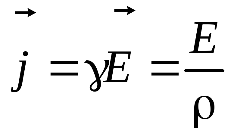 - Ohm's law in differential form. (4)
- specific electrical conductivity; - electrical resistivity.
Current density j at each point inside the conductor is equal to the product of the electrical conductivity of the conductor and the electric field strength at this point.
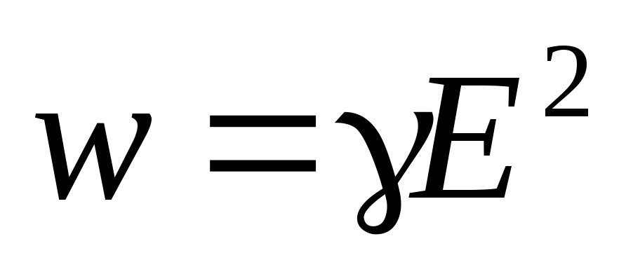 - Joule-Lenz law in differential form. (five)
The specific thermal power of the current in a conductor is equal to the product of its electrical conductivity by the electric field strength squared.
48 Electromotive force (emf)
Sources of current are called devices capable of creating a potential difference due to the work of forces of non-electrostatic origin.
Outside forces forces of non-electrostatic origin acting on charges from the side of the current source are called.
The nature of outside forces:
- chemical (galvanic cells);
- mechanical(generators;
- light energy (solar panels).
Electromotive force source(EMF) called:
the work that is spent by external forces to move a single positive charge from () terminals to (+) terminals inside the source;
potential difference at the output terminals of the current source at openexternal circuit.
 ,
(1)
,
(1)
Potential difference
Potential difference 1 2 on a chain section is the work done by the Coulomb forces when a positive charge moves.
Voltage U on the chain section is the work done by Coulomb and external forces when a positive charge moves.
 , [IN] ,
The voltage and potential difference are the same when there is no EMF in the circuit.
Resistance R reflects the degree of interference that free electrons experience when they move along a conductor under the influence of voltage. For conductor with specific resistance , length l and cross-sectional area S
 [Ohm]. (3)
Have the lowest resistivity
silver (  Omm),
Omm),
copper (  Ohmm) and aluminum (
  Omm).
Omm).
The resistance of metallic conductors increases with temperature:
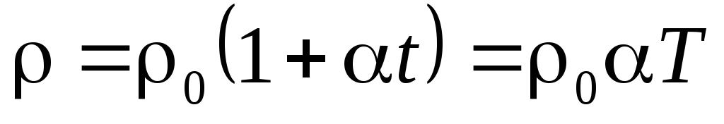 , (4
, (4
where  - resistivity at 0 0 С, and
  is a constant value for a given substance, called temperature coefficient of resistance... The change in resistance with temperature changes can be quite significant. So in an incandescent lamp, when a current passes through it and its spiral is heated, the resistance of the latter increases by more than 10 times.
49. To simplify the calculations of complex electrical circuits containing heterogeneous sections, use kirchhoff rules, which are a generalization of Ohm's law to the case of branched circuits. Branched chains can be distinguished anchor points (nodes), in which at least three conductors converge (Figure 4.10.1). The currents flowing into the node are considered to be positive; currents flowing out of the node are negative.
No charge accumulation can occur in the nodes of the DC circuit. this implies kirchhoff's first rule: The algebraic sum of the currents for each node in the branched circuit is zero:
|
Kirchhoff's first rule is a consequence electric charge conservation law... In a branched chain, you can always distinguish a number of closed paths, consisting of homogeneous and heterogeneous sections. Such closed paths are called contours... Different currents can flow in different parts of the dedicated circuit. In fig. 4.10.2 presents a simple example of a branched chain. The chain contains two nodes a and d, at which the same currents converge; therefore, only one of the nodes is independent (a or d).
Three contours can be distinguished in the chain: abcd, adef and abcdef Of these, only two are independent (for example, abcd and adef), since the third does not contain any new regions. Kirchhoff's second rule is a consequence of the generalized Ohm's law. Let us write down the generalized Ohm's law for the sections that make up one of the contours of the circuit shown in Fig. 4.10.2, for example abcd. To do this, at each site you need to set positive current direction and positive loop bypass direction... When writing the generalized Ohm's law for each of the sections, it is necessary to observe certain "rules of signs", which are explained in Fig. 4.10.3.
For sections of the contour abcd, the generalized Ohm's law is written in the form: For section bc: I1R1 \u003d Δφbc - \u200b\u200b1. For section da: I2R2 \u003d Δφda - 2. Adding the left and right sides of these equalities and taking into account that Δφbc \u003d - Δφda, we get :
The second Kirchhoff rule can be formulated as follows: the algebraic sum of the products of the resistance of each of the sections of any closed circuit of the branched DC circuit by the current in this section is equal to the algebraic sum of the EMF along this circuit. The first and second Kirchhoff rules, written for of all independent nodes and contours of the branched circuit, together give the necessary and sufficient number of algebraic equations for calculating the electrical circuit. For the circuit shown in fig. 4.10.2, the system of equations for determining three unknown currents I1, I2 and I3 has the form:
|
I1R1 + I2R2 \u003d - 1 - 2, |
|
- I2R2 + I3R3 \u003d 2 + 3, |
|
- I1 + I2 + I3 \u003d 0. |
Thus, Kirchhoff's rules reduce the calculation of a branched electrical circuit to solving a system of linear algebraic equations. This solution does not cause fundamental difficulties, however, it can be very cumbersome even in the case of fairly simple circuits. If, as a result of the solution, the current strength in some section turns out to be negative, then this means that the current in this section goes in the direction opposite to the chosen positive direction
50. Conduction electrons in a metal are in random motion. The fastest moving electrons, which have a sufficiently high kinetic energy, can escape from the metal into the surrounding space. At the same time, they perform work both against the forces of attraction from the side of the excess positive charge arising in the metal as a result of their escape, and against the repulsive forces from the side of previously emitted electrons, which form an electron "cloud" near the surface of the conductor. Dynamic equilibrium is established between the electron gas, in the metal and the electron "cloud". The work that needs to be done to remove an electron from a metal into a vacuum is called the work function. It is equal to, where e is the electron charge, is the output potential. The work function is produced by electrons - by reducing their kinetic energy. Therefore, it is clear that slowly moving electrons cannot escape from the metal. The work function depends on the chemical nature of the metal and the state of its contamination surface, traces of moisture, etc., change its value. For pure metals, the work function fluctuates within a few electron volts. A conduction electron can fly out of any metal if its energy exceeds the work function A of the electron from the metal. The phenomenon of the emission of electrons from heated metals is called thermionic emission.
The concentration of conduction electrons in a metal is very high; their thermal velocities at a given temperature are different and distributed, according to classical concepts, in accordance with Maxwell's law. This means that even at medium temperatures in a metal there are a sufficiently large number of conduction electrons capable of performing the work function and flying out of the metal. In this case, the work function is equal to the loss of kinetic energy
![]()
where m, e are the mass and charge of the electron, respectively, and are the electron velocities before and after leaving the metal. At ordinary temperatures, the number of electrons with a speed sufficient to escape is very small. There are several ways to impart additional energy to electrons, which is necessary to remove them from the metal: heating the conductor
(thermionic emission); irradiation of metals with visible and ultraviolet light (photoelectron emission); the effect of an accelerating external electric field (autoelectronic, or cold emission); bombardment of a metal with electrons or ions.
In order to obtain a significant flow of electrons, the so-called emitter is heated to temperatures of the order of 2000 ÷ 2500 K.
Contact potential difference - this is potential differencearising when two different conductorshaving the same temperature.
When two conductors with different work functions come into contact, electric charges appear on the conductors. And between their free ends there is potential difference... The potential difference between points located outside the conductors, in the vicinity of their surface is called the contact potential difference ... Since the conductors are at the same temperature, in the absence of an applied voltage, the field can exist only in the boundary layers ( Volta's rule). The internal potential difference (when the metals come into contact) and the external (in the gap) are highlighted. The value of the external contact potential difference is equal to the difference between the work functions referred to the electron charge. If the conductors are connected in a ring then EMF in the ring will be equal to 0. For different pairs of metals, the value of the contact potential difference ranges from tenths to several volts.
Electric. field K. p. etc., created by the contact volumetric charge, concentrated near the interface and in the gap between the conductors. The greater the concentration of conduction electrons in the conductors, the less the length of the contact region: in metals ![]() cm, in semiconductors up to cm. When a semiconductor is in contact with a metal, practically the entire region of the near-contact field is localized in the semiconductor.
cm, in semiconductors up to cm. When a semiconductor is in contact with a metal, practically the entire region of the near-contact field is localized in the semiconductor.
Volt (V, V) can be defined either as electrical voltage at the ends conductorrequired to generate heat in it power into one watt (W, W) at strength flowing through this conductor of constant current into one ampere (A), or as a potential difference between two points electrostatic field, when passing over a charge of magnitude 1 pendant (Cl, c) is committed work size 1 joule (J, J) ... Expressed in SI base units, one volt is equal to m² · kg · from −3 A −1 .
![]()
Volt (Russian designation: B; international: V) - in International System of Units (SI) unit electrical potential, potential difference, electrical voltage and electromotive force.
The potential difference between two points is 1 volt, if for moving charge size 1 pendant from one point to another over it must be done work size 1 joule... The volt is also equal to the electrical voltage, which causes a constant current by force 1 ampere at power 1 watt.
The unit is named after italian physics and physiologist Alessandro Volta (1745-1827), who invented volt pole, the first electric battery.
1 V \u003d (1/300) unit potential SGSE .
ELECTRODYNAMICS Direct electric current § 1. Electric current Electric charges in motion.All bodies and particles with mass experience gravitational attraction. The structure of the Universe is formed by the gravitational attraction of bodies of huge masses. Unlimited gravitational compression prevents these bodies from moving. The existence of bodies of finite dimensions is possible because between the particles of matter there are more powerful than gravitational forces of an electromagnetic nature: attraction and repulsion, which can balance each other. However, as we found out earlier (see F-10, § 78), the system of stationary (static) electric charges cannot be stable. Only a system of moving charges can be stable, just as the most seismically stable buildings are built on a movable support. Therefore, the next important step in studying the structure of matter is to consider the electromagnetic field of moving electric charges. An electric charge is a source of an electromagnetic field that spreads through space at the speed of light. The energy of the electromagnetic field, transferred in space from one charge to another, decreases with an increase in the distance between the charges. It is possible to change the energy of the electromagnetic interaction of charges, for example, by bringing one charge closer to another. The movement of charges in a conductor.The directed movement of charges in a conductor leads to the transfer of the energy of the electromagnetic field in space. Free charges are required for the existence of an electric current- current carriers,for example charged particles. 1 *
Electrodynamics Electricity- ordered (directed) movement of charged particles. In a conductor, the concentration of free charges, which can move throughout the entire volume of the conductor, without leaving its limits, is the greatest. Therefore, to transfer the energy of the electromagnetic field from one point in space to another, metal conductors are used, just as pipes are used to transport water. Directional movement of free charges in a conductor is possible under the action of an external electric field. In the absence of an external electric field (E \u003d0) the movement of charges in the conductor is chaotic (gray line in Fig. 1). This is how, for example, positive and negative ions move in electrolytes, electrons in metal conductors. After several collisions with other particles, charged particles can return to almost their original position. In the case when an external electric field is applied to the conductor (E *0), an additional Coulomb force acts on the charges. As a result of this, the positive charge, being attracted to the negative pole and repelling from the positive, acquires a velocity component v +
along the electric field strength, or directional speed.For a period of time t
a positive charge "drifts" a distance l +
= v +
t
in the direction of the electric field strength (black line in Fig. 1). The negative charge is displaced a distance l_ -
v_
t (v_
- drift velocity in the direction opposite to the electric field strength). In a conductor placed in an electric field, an ordered movement of charges is superimposed on a chaotic thermal one.
1>
Media movementcharges in the conductor. Overlay orderedthe movement of charges to a chaoticthermal motion inelectric field: and) positive; b) negative
Constant electric current
5 The direction of the ordered motion of positively charged particles is taken as the direction of the current. The direction of the current coincides with the direction of the strength of the electric field causing this current. INmetals, where current carriersare free, negatively charged electrons, the direction of the current is assumed to be opposite to the direction of the speed of their ordered motion (Fig. 2).
QUESTIONS The direction of the current in the metal
conductor opposite p
„ direction of motion of electrons 1. Give the definition of electric current r
r ka.
- Under what conditions does an electric current occur? Why is the movement of charged particles in a conductor in the absence of an external electric field chaotic? What is the difference between the motion of charged particles in a conductor in the absence and in the presence of an external electric field? How is the direction of the electric current chosen? In what direction do electrons move in a metal conductor through which an electric current flows?
At- "0 At
Electrodynamics Formula (1) in mathematics is a derivative. therefore dt (2) The current is the time derivative of the charge that has passed through the cross-section of the conductor over a period of time t. The unit of amperage (basic SI unit) - ampere(1 A):
1 A \u003d 1 C / s.
A precise definition of ampere will be given in § 25. Relationship between current strength and directional speed.In order to calculate the current strength, we find the charge Aq, flowing through the cross-section of a conductor (electrolyte) for a period of time At (fig. 3). During this time, only charges moving with a speed of v co-directionally with the strength of the external electric field, which are inside the cylinder with section S with the generatrix A1= vAt... Knowing concentration pcharged particles, you can find the number of charged particles in this volume N= nSvAt and determine their charge:
Aq = q() N = q 0 nSvAt,
Where q 0 - the charge of one particle. From formula (1), it follows that the current strength
/ = q 0 nSv.
(3) If the speed of movement of charges does not depend on time, i.e. v \u003d const, then the current strength / \u003d const. Constant electric current is a current whose strength does not change changes over time. Direct current is widely used in electrical circuits automobiles, as well as in microelectronics, etc.
| , Al= vAt | ||
| 3^ Electric current positive | q ° ± | |
| z + | ||
| spikes in electrolyte | 9 - * - w S,\\P&\\ jL. Aq | "" Unit of volume |
Constant electric current
7- What value characterizes the intensity of the directed motion of charged particles? Give the definition of current. How is the current strength related to the charge that has passed over time t
through the cross section of the conductor? In what units is the current strength measured? What electric current is called constant? How does the current strength depend on the concentration of charged particles?
- What charge will pass through the cross section of the conductor in 1 min if the current in the conductor is 2 A?
How many electrons pass through the filament of an incandescent lamp in 1 s when the current in the lamp is 1.6 A? A current of 1 A flows through the conductor throughout the year. Find the mass of electrons that have passed through the cross section of the conductor during this period of time. The ratio of the charge of an electron to its mass e / t e
\u003d 1.76 10 ^ 11 C / kg. In a conductor, the cross-sectional area of \u200b\u200bwhich is 1 mm 2, the current strength is 1.6 A. The concentration of electrons in the conductor is 10 23 m ~ 3 at a temperature of 20 ° C. Find the average speed of the directed motion of electrons and compare it with the thermal speed of electrons. j / QO Mlc
"
((£
B ^ b
"
In 4 s, the current in the conductor l "froze" from 1 to 5 A. Plot a graph of the current strength versus time. What charge passed through the cross-section of the conductor during this time?
Electrodynamic charges. An increase in the strength of the external electric field can be achieved by supplying additional charges to the conductor from the outside. These charges are generated and supplied to the conductor current source. The current source is a device that separates positive and negative charges. Galvanic cell.The separation of charges is possible as a result of the conversion of mechanical, thermal, chemical, light energy into electrical energy. So, in a galvanic cell, the charges on the electrodes turn out to be opposite due to the energy chemical reaction between electrodes and electrolyte. In the Volta cell, copper (Cu) and zinc (Zn) electrodes are immersed in a solution of sulfuric acid (H 2 S0 4). Negative ions SO | ~, which are in solution near electrically neutral copper and zinc electrodes, attract Cu 2+ and Zn 2+ ions located at the sites of the crystal lattice (Fig. 4, and).The attraction energy of unlike ions exceeds the binding energy of Cu 2+ and Zn 2+ ions in the crystal lattice of metal electrodes, so these ions pass into solution. Kinetic energy (E k ) Cu 2 + cu 2+ ions passing into solution is less than the kinetic energy (E k ) Zn 2+ ions of Zn 2+, since the binding energy E Si copper ions Cu 2+ in the crystal lattice exceeds the binding energy E Zn ions Zn 2+ (Fig. 5): (E ft) cu 2+ ~ E ± ~ ^ Cu "(£ fc) zn 2+ ~ E ± -E Zn" Where E ± - ion energy in solution. The more positive ions pass into the solution, the larger it becomes in modulus negative charge electrode (Fig. 4, b), which pre-
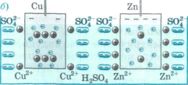
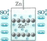 and) sol C ) "inI Si 2+ "so | - :.
;
With "X". H 2 SQ 4 A4 Redistribution of charges in the Volta galvanic cell
and) sol C ) "inI Si 2+ "so | - :.
;
With "X". H 2 SQ 4 A4 Redistribution of charges in the Volta galvanic cell Constant electric current
Have Ezn O "No. * W + i (p, B +0.34 -0.76 \u003d 1.1V ^5 Electromotiveelectroplating powerelement Volta prevents other ions from leaving it. The dissolution of the electrodes stops if the kinetic energy of positive ions is insufficient to overcome the potential difference of the electric double layer. This layer is formed positive charges ions in solution and with negative excess charges of electrodes: (- E ft) cu 2+ \u003d 9оFsi "(-Eft) zn 2 9 0| Metal | ||
| Lithium | ||
| Potassium | ||
| Sodium | ||
| Aluminum | ||
| Zinc | ||
| Iron | ||
| Tin | ||
| Lead | -o, c |
|
| Copper | ||
| Mercury | ||
| Silver | ||
| Platinum | ||
| Gold | ||
ё \u003d Fairies ~ Called electromotive force of a galvanic cellone or EMF. The copper electrode, which has a higher potential, turns out to be the source pole - anode,and zinc - negate Electrodynamics Insulation ammonium Carbonic
Zinc electrode
shell Why does electrostatic induction prevent direct current from flowing in a conductor? What is a current source? What is its role in the electrical circuit? What is a galvanic cell? Why does charge separation occur in a Volta galvanic cell? When does the dissolution of electrodes in the electrolyte solution stop? What is normal electrode potential? What is the potential difference across the terminals of a galvanic cell? Sources of current: and) miniature
Oxidemercury 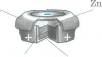
E ![]() electrolyteand) Chloride
electrolyteand) Chloride
battery; b) battery for
pocket flashlight ▲ 6
§ 4. Current sourcein the electrical circuit Outside forces.When a conductor connects the electrodes (poles) of a current source, an electric current flows through the conductor under the influence of a constant potential difference. Electrons moving from the cathode to the anode along the conductor reduce the potential difference between the electrodes, taking away the negative charge from the cathode and neutralizing the positive one at the anode. To maintain a constant potential difference, charges must accumulate at the poles of the source: positive charges in the electrolyte must move to the anode, and negative charges to the cathode. Such a movement in the direction opposite to the action of the Coulomb repulsive forces between the same charges can occur only under the action of forces of a non-electrical nature, called outside forces.