Discharging a capacitor with direct current. Study of the process of charging and discharging a capacitor
The purpose of the work is to study the process of discharging a capacitor on active resistance, determination of relaxation time, estimation of capacitor capacity.
Instruments and accessories: laboratory setup, power supply, microammeter, test capacitor, stopwatch.
An electrical capacitor or simply a capacitor is a device capable of storing and releasing (redistributing) electric charges. A capacitor consists of two or more conductors (plates) separated by a dielectric layer. As a rule, the distance between the plates, equal to the thickness of the dielectric, is small compared to the linear dimensions of the plates, therefore the electric field that arises when the plates are connected to a voltage source U, is almost completely concentrated between the plates. Depending on the shape of the plates, capacitors are flat, cylindrical, or spherical.
The main characteristic of a capacitor is its capacity C, which is numerically equal to the charge Q one of the plates at a voltage equal to unity:
Let the capacitor have a capacity C included in the electrical circuit (Fig. 1),
Fig.1
containing the source DC voltage U 0, key K and resistor (active resistance) R. When the key is closed K the capacitor will charge to voltage U 0. If then the key K open, the capacitor will begin to discharge through the resistor R and in the chain there will be electric current I. This current changes over time. Considering the processes occurring in the circuit to be quasi-stationary, we apply the laws of direct current to this circuit.
Let's find the dependence of the discharge current I from time to time t. To do this, we will use Kirchhoff’s second rule as applied to the circuit R-C(Fig. 2). Then we get:
, (1)
Where I– electric current in the circuit, Q– capacitor charge C. Substituting into equation (1) the value of the discharge current I = - dQ / dt, we obtain a first order differential equation with separable variables:
.
(2)
After integrating equation (2) we find
Q(t) = Q 0 e -t/τ , (3)
Where Q 0– initial value capacitor charge, τ = R.C.– a constant having the dimension of time. It is called relaxation time. Through time τ , the charge on the capacitor decreases by e times.
Having differentiated equation (3), we find the law of change in the discharge current I(t):
I(t) = e -t/τ .
I(t) = I 0 e -t/τ, (4)
Where I 0 = - initial current value, i.e. current at t = 0.
Figure 3 shows two dependences of the discharge current I from time to time t, corresponding to two different values of active resistance R 1 and R 2 (τ 1 < τ 2).
Description of the laboratory setup
In this laboratory work, it is proposed to study the process of discharging a capacitor using an experimental setup, the diagram of which is shown in Fig. 4.
It consists of a constant voltage source U 0, containers C, resistors R 1 , R 2 ,R 3 and microammeters. Since resistors R 1 , R 2 ,R 3 are connected in series, the active resistance of the circuit can be changed using jumpers P, short-circuiting the resistors in turn R 1 , R 2 or both together.
Measurement order. Processing of measurement results
Assemble an electrical circuit according to the diagram in Fig. 4 and, according to the teacher’s instructions, select the required value of the circuit resistance R.
Lock the key K and charge the capacitor C to tension U 0. When the capacitor is fully charged, the microammeter will show the maximum current value I 0.
Unlock the key K and start the stopwatch at the same time. Measure time t 0, during which the microammeter readings will decrease by 10 times. Define the time interval Δ t ≈ t 0 / 10.
Re-lock the key K and charge the capacitor.
Unlock the key K and record microammeter readings at time intervals Δt, 2Δt, 3Δt, etc. until time 10Δt. Perform such measurements three times, and record the results in Table 1.
Calculate (average current value) and ratio.
Table 1
| t,s | 0 | Δt | 2Δt | 3Δt | 4Δt | 5Δt | 6Δt | 7Δt | 8Δt | 9Δt | 10Δt |
| I 1 | |||||||||||
| I 2 | |||||||||||
| I 3 | |||||||||||
| /I 0 |
Repeat the experiments three times for different values. R.
Security questions:
What is a capacitor? Derive the formula for the capacitance of a flat capacitor.
Derive the formula for the capacitance of a spherical capacitor.
Laboratory work No. 6
STUDYING THE PROCESS OF CHARGING AND DISCHARGING A CAPACITOR
PURPOSE OF THE WORK
Study of the processes of charging and discharging capacitors in R.C.- circuits, familiarization with the operation of devices used in pulsed electronic technology.
THEORETICAL BASIS OF WORK
![]() Let's consider the diagram shown in Fig. 1. The circuit includes a direct current source, an active resistance and a capacitor, in which we will consider the charge and discharge processes. We will analyze these processes separately.
Let's consider the diagram shown in Fig. 1. The circuit includes a direct current source, an active resistance and a capacitor, in which we will consider the charge and discharge processes. We will analyze these processes separately.
Capacitor discharge.
Let first a current source e be connected to a capacitor C through a resistance R. Then the capacitor will charge as shown in Fig. 1. Let's move key K from position 1 to position 2. As a result, the capacitor is charged to voltage e, will begin to discharge through resistance R. Considering the current positive when it is directed from the positively charged plate of the capacitor to the negatively charged one, we can write
http://pandia.ru/text/78/025/images/image003_47.gif" width="69 height=25" height="25">, , (1)
Where i– instantaneous value of current in the circuit, the minus sign of which indicates that the appearance of current in the circuit i associated with a decrease in charge q on the capacitor;
q And WITH– instantaneous values of charge and voltage on the capacitor.
Obviously, the first two expressions represent the definitions of current and electrical capacity, respectively, and the last is Ohm's law for a section of the circuit.
From the last two relations we express the current strength i as follows:
http://pandia.ru/text/78/025/images/image006_31.gif" width="113" height="53 src=">. (2)
18. Why is there no DC source shown in the circuit diagram in this installation?
19. Is it possible to use a generator in this installation? sinusoidal voltage, sawtooth voltage?
20. What frequency and duration of pulses should the generator produce?
21. Why is active resistance needed in this circuit? R? What should its size be?
22. What types of capacitors and resistors can be used in this installation?
23. What values can capacitance and resistance have in this circuit?
24. Why is oscilloscope signal synchronization needed?
25. How do you achieve the optimal appearance of the signal on the oscilloscope screen? What adjustments apply?
26. What is the difference between the charge and discharge circuits of a capacitor?
27. What measurements need to be taken to determine the capacitance of the capacitor in R.C.-chains?
28. How to evaluate measurement errors during operation of the installation?
29. How to improve the accuracy of determining relaxation time R.C.-chains?
30. Name ways to improve the accuracy of determining the capacitance of a capacitor.
Charging and discharging a capacitor
1 Charging a dielectric capacitor
The fallacy of the current interpretation of the operation of a capacitor is especially obvious. It is based on the presence in electrical circuit positive and negative charges. The carriers of these charges are known: proton and electron. However, they are also known to sense each other's presence at distances a thousand times the size of an electron and a million times the size of a proton. Even such a distant neighborhood ends with the process of formation of hydrogen atoms, which exist only in a plasma state at temperatures up to 5000 C. This occurs, for example, in the processes of removing electrons and protons from the Sun and their subsequent combination into hydrogen atoms. So the joint presence of protons and electrons in a free state in conductors is completely excluded, therefore the positive and negative potentials on the plates of a dielectric capacitor are a mistake of physicists. Let's fix it.
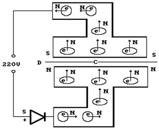
Now we will see that the plates of a dielectric capacitor are charged not by opposite electric polarities, but by opposite magnetic polarities. In this case, the plus functions belong to the south magnetic pole of the electron, and the minus functions to the north. These poles form polarity, but not electric, but magnetic. Let's follow the charging process of a dielectric capacitor to see how the magnetic poles of an electron form the magnetic polarity of its plates. It is known that between the plates of a dielectric capacitor there is dielectric D (Fig. 1, a).
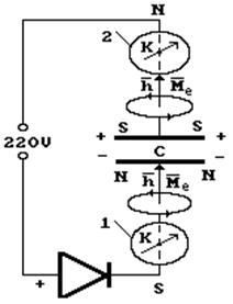
The experimental diagram for charging a dielectric capacitor is shown in Fig. 1, a. The most important requirement for the diagram is its orientation from south (S) to north (N). To ensure complete isolation of the capacitor from the network after charging, it is advisable to use an electrical plug plugged into a 220 V power outlet.
Immediately after the diode, compass 1 (K) is shown, placed on the wire going to capacitor C. The arrow of this compass, deviating to the right at the moment the plug is turned on, shows the direction of movement of electrons (Fig. 1) from point S to the bottom plate of the capacitor. Here it is appropriate to pay attention to the generality of information about the behavior of electrons in wires presented in Fig. 1.
Rice. 1. Scheme of our capacitor charging experiment
Above compass 1 (Fig. 1) is a direction diagram magnetic field around a wire formed by electrons moving in it.
Thus, electrons passing through the diode arrive at the bottom plate of the capacitor with oriented spin vectors
and magnetic moments to its inner surface (Fig. 1). As a result, a north magnetic potential (N) is formed on this surface.It is quite natural that electrons will come to the inner surface of the upper plate of the capacitor from the network, oriented south magnetic poles(S). Proof of this is the experimental fact of the deviation of the upper compass needle 2 (K) to the right (Fig. 1). This means that electrons moving from the network to the upper plate of the capacitor are oriented with their south magnetic poles (S) in the direction of movement (Fig. 2).
Thus, the orientation of electrons on the plates of a dielectric capacitor is ensured by the permeability of their magnetic fields through the dielectric. The potential on the capacitor plates is one - negative and two magnetic polarities: the north and south magnetic poles.
In Fig. Figure 2 shows a diagram explaining the orientation of electrons moving to the plates of capacitor C. Electrons arrive at the bottom plate of the capacitor with their north magnetic poles (N) oriented toward its inner surface (Fig. 2). Electrons oriented with the south magnetic poles (S) arrive at the inner surface of the upper plate of the capacitor.
Rice. 2. Diagram of the movement of electrons to the plates of a dielectric capacitor
So electrons, the only carriers of electricity in wires, form on the capacitor plates not opposite electrical polarity, but opposite magnetic polarity. There are no protons on the plates of a dielectric capacitor - carriers of positive charges.
2 Discharging a dielectric capacitor
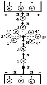
The process of discharging a dielectric capacitor into resistance is the next experimental proof of the reality of the identified model of the electron and the fallacy of the prevailing ideas that opposite electric charges are formed on the plates of a dielectric capacitor (Fig. 3).
The diagram of the deflection of compass needles (K) 1, 2, 3 and 4 when the capacitor is discharged to resistance R at the moment switch 5 is turned on is shown in Fig. 3.
As you can see (Fig. 1 and 3), at the moment the capacitor discharge process is turned on, the magnetic polarity on the capacitor plates changes to the opposite and the electrons, turning around, begin to move towards resistance R (Fig. 2, 3).
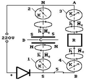
Rice. 3. Diagram of deflection of compass needles (K) at the moment of capacitor discharge
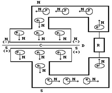
Rice. 4. Diagram of the movement of electrons from the capacitor plates to the resistance R when discharging a dielectric capacitor
Electrons coming from the upper plate of the capacitor are oriented with the south magnetic poles in the direction of movement, and from the bottom - with the north ones (Fig. 4). Compasses 3 and 4, installed on a set of VA wires oriented from south to north, clearly record this fact by deflecting the arrows to the right, thereby proving that the vectors of the spins and magnetic moments of all electrons in these wires are directed from south to north (Fig. 3, 4 ).
3 Charging the electrolytic capacitor
When analyzing the charging process of an electrolytic capacitor, it must be taken into account that the electrolytic capacitor contains ions that have positive and negative charges, which control the process of potential formation on the plates of an electrolytic capacitor. Now we will see that the presence of an electrolyte in a capacitor does not lead to the appearance of positive charge carriers, that is, protons, in the wires.
An electron is a hollow torus that has two rotations: relative to the axis of symmetry and relative to the annular axis of the torus. Rotation relative to the annular axis of the torus forms the magnetic field of the electron, and the directions of the magnetic power lines This field is formed by two magnetic poles: northern N and southern S.
The rotation of the electron about the central axis is controlled by the kinetic torque
- vector quantity. The magnetic moment of an electron is also a vector quantity, coinciding with the direction of the kinetic moment vector. Both of these vectors form the north magnetic pole of the electron (N), and at the other end of the central axis of its rotation the south magnetic pole (S) is formed. The formation of such a complex electron structure is controlled by more than 20 constants.In Fig. 5, and the ion orientation is shown as an example
V electric field. A positively charged proton with its north magnetic pole is directed towards the negatively (-) charged plate. Since the vectors of the magnetic moments of the electron and proton in the hydrogen atom are directed oppositely, the axial electrons 2 and 3 of the oxygen atom, joining in a chain with the protons and neutrons of the nucleus of the oxygen atom, form the same magnetic polarity at the ends of the ion axis (Fig. 5, a). This pattern of magnetic polarity is also preserved along the axis of the cluster consisting of these ions (Fig. 5, b). The logic of all processes is preserved only if the actions of the charges and magnetic fields of the electron and proton are equivalent.Let's pay attention to main feature structures of the hydrogen atom: vectors of electron magnetic moments
and proton are directed along the atomic axis in opposite directions. This is due to the fact that the approach of a proton and an electron is limited by their magnetic poles of the same name. The distribution of magnetic fields in the ion structure is shown in Fig. 5, a. As you can see, at the ends of the axis of this ion are the north magnetic poles of the electron and proton. Ion clusters also have a similar polarity (Fig. 5b). It is quite natural that the number of ion clusters forming an electrical circuit in a dielectric capacitor is very large.If the role of the electrodes shown in Fig. 5, a, the plates of the capacitor are made, then when it is charged, the electrons coming from the external network are oriented with the south magnetic poles at the left plate of the capacitor and the north magnetic poles at the right plate. This is due to the fact that electrons bring their opposite magnetic poles together, and the approach of an electron to a proton is limited by magnetic poles of the same name.
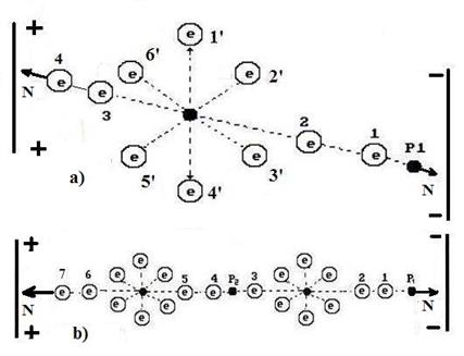
Rice. 5. a) – diagram of the ion; diagram of a cluster of two ions
In Fig. 6, and the ion orientation is shown as an example
in a charged capacitor. A positively charged proton with its north magnetic pole is directed towards the lower negatively (-) charged plate of the capacitor. Since the vectors of the magnetic moments of the electron and proton in the hydrogen atom are directed oppositely, the axial electrons 2 and 3 of the oxygen atom, joining in a chain with the protons and neutrons of the nucleus of the oxygen atom, form the same magnetic polarity at the ends of the ion axis. This pattern of magnetic polarity is also preserved along the axis of the cluster consisting of these ions. The logic of all processes is preserved only if the actions of the charges and magnetic fields of the electron and proton are equivalent.Let's reverse special attention due to the fact that the upper plate of the capacitor (Fig. 6, a) has electrons on both sides and therefore it seems that they repel each other. However, it must be borne in mind that when clusters of electrons are formed, they are connected to each other by opposite magnetic poles, and identical electric charges limit their approach, therefore the contact of the ion with the upper plate of the capacitor is ensured by the opposite magnetic poles of the electrons. The bottom plate of the capacitor has opposite electric charges, which bring the proton of the hydrogen atom and the electron of the capacitor plate closer together. But this rapprochement is limited to their magnetic poles of the same name. This explains these apparent contradictions.
Rice. 6. a) diagram of ion orientation in an electrolytic capacitor; b ) capacitor charging circuit
Thus, the plates of an electrolytic capacitor are charged with opposite electrical polarity and opposite magnetic polarity at the same time. In this case, the plus functions belong to the south magnetic pole of the electron, and the minus functions to the north. These poles form both the electric and magnetic polarities on the capacitor plates. Let's follow the charging process of a capacitor to see how the magnetic poles of the electron and proton form the magnetic and electric polarities of its plates.
The experimental diagram for charging a capacitor is shown in Fig. 5, b. The most important requirement for the diagram is its orientation from south (S) to north (N). Immediately after the diode, compass 1 (K) is shown, placed on the wire going to capacitor C. The arrow of this compass, deviating to the right at the moment the voltage is turned on, shows the direction of movement of electrons (Fig. 5, b) from point S to the bottom plate of capacitor C. Above compass shows a diagram of the direction of the magnetic field around a wire formed by electrons moving in it.
Thus, electrons passing through the diode arrive at the bottom plate of the capacitor with oriented spin vectors
and magnetic moments to its inner surface (Fig. 5, b). As a result, a north magnetic potential (N), equivalent to a negative potential (-), is formed on this surface.It is quite natural that electrons will come from the network to the upper plate of the capacitor with oriented south magnetic poles (S). Proof of this is the experimental fact of the deviation of the upper compass needle 2 (K) to the right (Fig. 5, b). This means that the electrons moving along the wire to the top plate of the capacitor are oriented with their south magnetic poles (S) in the direction of movement.
In Fig. Figure 4 shows a diagram explaining the orientation of electrons moving to the plates of capacitor C when it is charging. Electrons arrive at the bottom plate of the capacitor with their north magnetic poles (N) oriented toward its inner surface. Electrons arrive at the inner surface of the upper plate of the capacitor with oriented south magnetic poles (S).
Let us pay attention to the fact that the directions of orientation of electrons when they move to the plates of a dielectric capacitor (Fig. 4) are similar to the orientation of electrons when they move to the plates of an electrolytic capacitor (Fig. 6, b).
So electrons, the only carriers of electricity in wires, form on the plates of an electrolytic capacitor both opposite electrical polarity (+ and -) and opposite magnetic polarity (S and N) at the same time.
4 Discharging the electrolytic capacitor
The process of discharging a capacitor into resistance is the next experimental proof of the correctness of the new interpretation about the direction of movement of electrons (Fig. 3) in wires and the fallacy of the prevailing ideas that only opposite electric charges are formed on the capacitor plates.
Schemes for deflection of compass needles (K) 1, 2, 3 and 4 when discharging the capacitor to resistance R at the moment switch 5 is turned on are shown in Fig. 3.
As can be seen (Fig. 2), at the moment the capacitor discharge process is turned on, the magnetic and electric polarities on the capacitor plates change to the opposite and the electrons, turning around, begin to move towards resistance R (Fig. 2).
Electrons coming from the top plate of the capacitor are oriented with the south magnetic poles in the direction of movement, and from the bottom - with the north. Compasses 3 and 4, installed on a set of wires VA (Fig. 3), oriented from south to north, will clearly record the fact by deflecting the arrows to the right, thereby proving that the vectors of the spins and magnetic moments of all electrons in these wires are directed from south to north.
As you can see, the pattern of electron motion during the discharge of a dielectric capacitor is similar to the pattern of electron motion during the discharge of an electrolytic capacitor (Fig. 3).
Now let’s imagine the moments of opening or closing an electrical circuit, at which, as is known, the voltage increases sharply. The reason for this phenomenon is that at the moment the electrical circuit opens, there is a phase when part of this circuit is formed by air ions. The total number of electrons of these ions is significantly more quantity free electrons in the wire. As a result, they increase the electrical potential for the period of time when the electrical circuit is formed by air ions. This is clearly visible in Fig. 5, a, where the ion is shown
between the plates of the capacitor. The area of the broken electrical circuit is filled with the same ions.