A simple DIY digital voltmeter. Pointer voltmeter
A digital ammeter on LEDs is a convenient way to display information, in which not only the module of the measured value matters (which, by the way, is much more convenient to determine not by the deviation of the dial indicator, but by the size of the bar graph, or using a mini-display), but also the frequency changing this parameter.
Description of the scheme
LEDs are no different high power, but use them in low-current electrical circuits acceptable and appropriate. As an example, we can consider a circuit for obtaining a digital ammeter to determine the current strength in a car battery, with a nominal value range of 40...60 mA.
Variant of the appearance of an ammeter on LEDs in a column
The number of LEDs used will determine the threshold current value at which one of the LEDs will turn on. You can use LM3915 or a microcontroller with suitable parameters as an operational amplifier. The input will be supplied with voltage through any low-resistance resistor.
It is convenient to display the measurement results in the form of a bar chart, where the entire practically used current range will be divided into several segments of 5...10 mA. The advantage of LED is that the circuit can use elements of different colors - red, green, blue, etc.
To operate a digital ammeter you will need the following components:
- Microcontroller type PIC16F686 with 16-bit ADC.
- Configurable jumpers for final signal output. Alternatively, DIP switches can be used as electronic shunts or signal shorts in conventional electronic circuits.
- Power supply DC, which is designed for an operating voltage of 5 to 15 V (if there is a stable voltage, which is controlled by a voltmeter, 6 V is also suitable).
- Contact board where you can place up to 20 SMD LEDs.
 Electrical diagram ammeter on LED sources
 Sequence of placement and installation of the ammeter
The current input signal (no more than 1 A) is supplied from a stabilized power supply through a shunt resistor, permissible voltage which should not be more than 40...50 V. Then, passing through the operational amplifier, the signal goes to the LEDs. Since the value of the current changes during the passage of the signal, the height of the column will change accordingly. By controlling the load current, you can adjust the height of the diagram, obtaining results with varying degrees of accuracy.
Mounting the board with SMD components, at the user’s request, can be placed either horizontally or vertically. Before starting calibration, the viewing window must be covered with dark glass (a filter with a multiplicity of 6...10 x of a regular welding helmet is suitable).
Calibration of a digital ammeter consists of selecting the minimum current load value at which the LED will light. The setting is varied experimentally, for which a resistor with a small (up to 100 mOhm) resistance is provided in the circuit. The error in readings of such an ammeter usually does not exceed several percent.
Did you know that you can convert an old voltmeter into an ammeter? How to do this - watch the video:
How to set the adjustment resistor
To do this, the current strength that passes through a specific LED is sequentially set. A regular tester can be used as a control device. A voltmeter is included in the circuit before the microcontroller, and an ammeter after it. To eliminate the influence of random ripples, a smoothing capacitor is also connected.
A practical advantage of making the device yourself (there should be no less than four LEDs) is the stability of the circuit with significant changes in the initially specified current range. Unlike conventional diodes, which when short circuit fail, the LEDs simply do not light up.
LED diodes, like current meters in a car battery, not only save charge and preserve batteries, but also allow you to read the readings in a more convenient way.
A digital voltmeter can be built in a similar way. 12 V elements are suitable as light sources for this application, and the presence of an additional shunt in the voltmeter circuit will allow more efficient use of the entire height of the bar graph.
The article describes a voltmeter with a measurement limit of 50 volts, made on a PIC16F676 or how to use the ADC of this microcontroller.
Scheme
A voltage divider is assembled on resistors R1 and R2, and a multi-turn construction resistor R3 is used to calibrate the voltmeter. Capacitor C1 protects the voltmeter from impulse noise and smoothes the input signal. Zener diode VD1 serves to limit the input voltage at the microcontroller input so that the MK input does not burn out when the input voltage is exceeded.
An inverting element is assembled on transistor VT1 (KT3102 or SMD version BC847) and resistors R11, R12 and R13, which lights up the point on the indicator along with the second digit.
The circuit uses an indicator with a common anode BA56-12GWA, which is connected to the MK through current-limiting resistors. This indicator is different low consumption current When using more powerful indicators (larger segments or different colors), it is recommended to place keys on the anodes.
In an endless loop, data is constantly received from the ADC, converted and output to a 7-segment indicator in PWM mode.
Signet
The voltmeter is adjusted using trimming resistor R3 (it is advisable to use a multi-turn).
.
Attention
Some programmers have discovered a problem with damaged microcontrollers. This is expressed in the fact that they overwrite the factory calibration constant of the internal RC chain, after which the MK begins to work incorrectly or stops working altogether. Therefore, before flashing the microcontroller firmware, first read its memory and write out the last word (2 bytes) from the controller’s flash memory. After flashing, check whether the value is saved; if not, flash the controller, but with the previously written calibration constant.
Firmware
I present to you the new version of voltmeter firmware V3.2 dated April 10, 2012. The first digit is removed if it is equal to 0 and in the 100V version the maximum indicator value is set to 99.9V.
Common anode:
Common cathode:
Verified firmware version V3.1 - indicator flickering has been removed.
Common anode:
Common cathode:
Old firmware versions (common anode):
New firmware added 04/10/2012
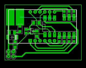
And now a little practice, what can be done from this diagram, here is one of the options....
The signet includes illumination of pictograms according to my device.

Transferring etching tracks
The photo shows an example of using photo paper. As you can see, the toner is transferred completely and without soaking. The paper just flies off.
Further etching and tinning of the tracks
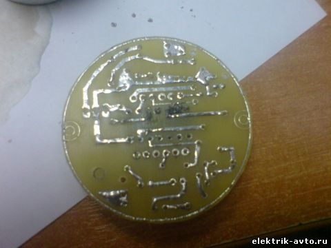
ready
An hour later the payment was collected. When laying out the board, it was decided to make the screen, like the microcontroller, dismountable in the socket and not solder in.
The idea turned out to be very successful since during normal installation the screen occupied 50% of the space on the printed circuit board. When installed in a socket, the screen is located at a height of 8-10 mm above printed circuit board which made it possible to place a full-fledged voltage stabilizer and some radio elements under it. This can be clearly seen in the following photographs.

Placement of radio components
![]()
top view with screen
But it is precisely in this case that we need to place this device.
device body vaz 2106
The front panel was made using the same method. disc box and film with pictograms cut at an advertising agency.

Front panel
Later, I decided to abandon attaching the front part to the board with screws and settled on film. Reliability is not necessary here; you just need to ensure that the panel does not move relative to the screen when assembling the device.

To fix the board in the case and prevent the board from shorting to the case, I cut off a piece of vibration or noise insulation and glued it around the bottom of the case.
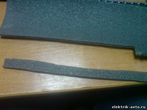
Section for gluing

Sticking
Here is a view of the assembled board with the front panel.

This is how the device is centered in the case.
A car voltmeter is a useful device that allows a motorist to always know what voltage is in the on-board network of his vehicle. Many car enthusiasts today are interested in the question of how to build such a device themselves at home. Below you can find step by step instructions on making the device with your own hands.
Characteristics of a car voltmeter
How to make a voltmeter? How should a made electronic voltmeter be connected to the cigarette lighter, what is the connection diagram? First, let's take a look at the main characteristics of the device.
Device Description
As we have already said, a digital voltmeter is designed to measure voltage. An analog device is a device equipped with a pointer indicator and a scale. Today, such devices are used very rarely, in lately Digital devices are becoming increasingly popular.
Species

As for the types themselves, you can find either simple devices or combined ones on sale.
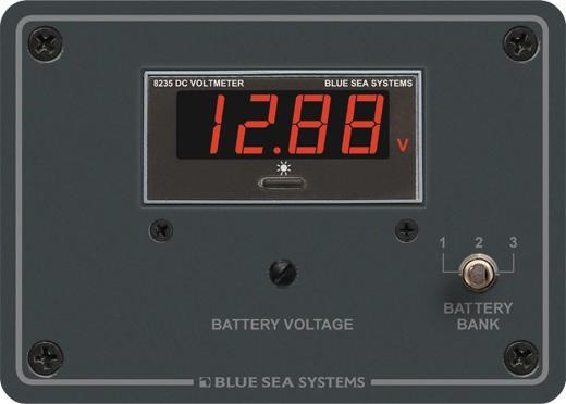
- Simple. Such a device is characterized by comparatively small in size, as a result of which its installation is allowed virtually anywhere in the vehicle. Therefore, a voltmeter of this type is usually connected to the cigarette lighter. Thus, the device allows you to monitor the voltage level of the battery both when the engine is turned off and when the engine is running. If you decide to install a voltmeter with your own hands, then it will be useful for you to know that when the engine is off, the voltage should be 12.5 volts, while when the engine is running - 13.5-14.5 volts.
If this parameter is higher or lower, you will need to diagnose the on-board network of the machine. A voltmeter in a car will be indispensable, be it a dial version or a digital car one, it will become an indispensable attribute for those who like to relax in nature. With its help, you will always know what voltage is in the network of your vehicle and how to prevent it from falling below normal. It's no secret that relying on standard low battery indicators is not entirely correct, since such devices usually warn the driver when it is too late to take any action. The voltmeter circuit can be connected to a special remote display, which can be installed anywhere in the car, for example, directly in the center console. - Combined. As for combined instruments, they can be additionally equipped with thermometers, tachometers, ammeters, etc. Thanks to the thermometer, the driver will always be able to know what the temperature is inside the car or outside, in the engine compartment of the vehicle. With the help of a tachometer, the car enthusiast will always have the opportunity to monitor the number of engine revolutions. As a rule, if you buy a combined gadget with a tachometer, the kit should include all the necessary sensors that allow you to measure this indicator from 50 degrees below zero to 120 degrees of heat. In general, the procedure for installing a device of this type in your car is not a particularly complicated procedure, which you can easily cope with on your own.
Guide to making a homemade voltmeter in a car
Scheme

So, if you decide to build a car voltmeter from a calculator, an LED voltmeter from lamps, or any other, you should at least understand this topic. A lamp voltmeter or an LED voltmeter can be purchased at any automotive electronics store. But if you decide to do everything yourself, then keep in mind that simply taking a board and installing it in a car is not an option; you need some knowledge in the field of electronics. We will look at an example of a digital device circuit in a car, in particular, a voltmeter on pic16f676. Below is a diagram of a device with a measurement limit of 50 volts, this is quite enough.
A voltage divider is installed on two resistors - R1 and R2, and element R3 is intended for calibrating the device. Another component C1 (capacitor) is used to protect the system from signal interference, and it also allows you to smooth the input pulse. VD1 is a zener diode designed to limit the input voltage level at the controller input; its use is necessary to ensure that the MK input does not burn out when the network voltage increases.
The inverting component of the device is assembled using resistors R11-R13, as well as transistor VT1. The inverter lights the dot directly on the indicator itself along with the second digit. An indicator with an anode, characterized by minimal current consumption, is connected to the MK. As for setting up the device itself, it is carried out using a tuning resistor R3 (the author of the video on how to build a voltmeter with your own hands is Ruslan K).
DIY connection
To connect a voltmeter on a microcontroller to your car yourself, you first need to decide on the installation location. Installation is carried out in any place convenient for the driver. In our case, we will install a voltmeter in the car in the center console.
The process is described using the example of a VAZ 2113 car:
- Remove the plastic trim to the right of the instrument panel, above the radio. In the case of the VAZ 2113, this plastic can be removed without problems; it is attached to plastic clips, so when dismantling, be careful not to damage them.
- Using an electric jigsaw, you need to cut a rectangular hole on the plug. Cut the hole according to the dimensions of your voltmeter display - the device should fit perfectly into the cut hole.
- WITH reverse side plastic plug, install the device. To begin with, you can fix it using ordinary stationery rubber bands. Of course, you won’t drive like this, because it’s not at all aesthetically pleasing and will only spoil the appearance of the car’s interior. Therefore, the free space on the back side will need to be filled with a special plumbing sealant so that the board adheres well to the plug. When the voltmeter sets, the rubber bands can be removed.
- To connect the device to the on-board network, you can use a special connector from the computer power supply. It may or may not fit - if it doesn't fit, you'll have to resort to soldering. Reinstall the plastic cover around the display, you can add an additional frame to improve appearance screen. It is important that the voltmeter does not distract the driver while driving, so if the digit light is too bright, something needs to be done about it. You can darken the screen using regular varnish or a small piece of tint film.
- You can connect the device either directly to the battery so that the voltmeter always functions, or to the ignition. The second option is more acceptable, in this case the device will be activated when the car radio is turned on, that is, you can always monitor the voltage status when the audio system is turned on.


Video “Installing a digital voltmeter with your own hands”
You can learn more about how to install a digital voltmeter on your own from the video below (the author of the video is Auto World).
Ammeters are devices that are used for the purpose of determining the current in a circuit. Digital modifications are made on the basis of comparators. They differ in measurement accuracy. It is also important to note that the devices can be installed in circuits with direct and alternating current.
Based on the type of construction, there are panel-mounted, portable, and built-in modifications. There are pulse and phase-sensitive devices according to their intended purpose. IN separate category selective models are highlighted. In order to understand the devices in more detail, it is important to know the structure of the ammeter.
Ammeter circuit
A typical digital ammeter circuit includes a comparator along with resistors. A microcontroller is used to convert the voltage. It is most often used with reference diodes. Stabilizers are installed only in selective modifications. Broadband filters are used to increase measurement accuracy. Phase devices are equipped with transceivers.

DIY model
Assembling a digital ammeter with your own hands is quite difficult. First of all, this will require a high-quality comparator. The sensitivity parameter must be at least 2.2 microns. It must maintain a minimum resolution of 1 mA. The microcontroller in the device is installed with reference diodes. The display system is connected to it through a filter. Next, to assemble a digital ammeter with your own hands, you need to install resistors.
Most often they are selected as a switched type. The shunt in this case should be located behind the comparator. The division factor of the device depends on the transceiver. If we talk about a simple model, then it is used of the dynamic type. Modern devices are equipped with ultra-precise analogues. A regular lithium-ion battery can serve as a source of stable current.

DC devices
The digital DC ammeter is produced on the basis of highly sensitive comparators. It is also important to note that stabilizers are installed in the devices. Resistors are only suitable for the switched type. The microcontroller in this case is installed with reference diodes. If we talk about parameters, the minimum resolution of devices is 1 mA.
AC Modifications
Ammeter (digital) AC you can do it yourself. Microcontrollers in the models are used with rectifiers. To increase the measurement accuracy, broadband filters are used. The shunt resistance in this case should not be less than 2 ohms. The sensitivity of resistors must be 3 microns. Stabilizers are most often installed expansion type. It is also important to note that you will need a triode for assembly. It must be soldered directly to the comparator. The permissible error of devices of this type fluctuates around 0.2%.
Pulse measuring instruments
Pulse modifications are distinguished by the presence of counters. Modern models are produced on the basis of three-bit devices. Resistors are used only of the orthogonal type. As a rule, their division coefficient is 0.8. The permissible error, in turn, is 0.2%. The disadvantages of the devices include sensitivity to environmental humidity. They are also prohibited from being used for sub-zero temperatures. Assembling the modification yourself is problematic. Transceivers in the models are used only of the dynamic type.
Phase-sensitive modification device
Phase-sensitive models are sold at 10 and 12 V. The permissible error parameter for the models fluctuates around 0.2%. Counters in devices are used only of the two-digit type. Microcontrollers are used with rectifiers. Ammeters of this type are not afraid of high humidity. Some modifications have amplifiers. If you are assembling a device, you will need switched resistors. A regular lithium-ion battery can be a source of stable current. A diode is not needed in this case.
Before installing the microcontroller, it is important to solder the filter. A converter for lithium-ion will need a variable type. Its sensitivity indicator is at the level of 4.5 microns. When cutting the circuit, you need to check the resistors. The division coefficient in this case depends on the throughput of the comparator. The minimum pressure of devices of this type does not exceed 45 kPa. The current conversion process itself takes about 230 ms. The speed of the clock signal depends on the quality of the counter.

Selective device diagram
The selective digital DC ammeter is manufactured on the basis of high-capacity comparators. The acceptable error of the models is 0.3%. The devices operate on the principle of single-stage integration. Counters are used only of the two-digit type. Stable current sources are installed behind the comparator.
Resistors are used of the switched type. To assemble the model yourself, you will need two transceivers. Filters in this case can significantly increase the accuracy of measurements. The minimum pressure of the devices is around 23 kPa. A sharp drop in voltage is observed quite rarely. The shunt resistance, as a rule, does not exceed 2 ohms. The current measuring frequency depends on the operation of the comparator.
Universal measuring instruments
Universal measuring instruments are more suitable for household use. Comparators in devices are often installed with low sensitivity. Thus, the permissible error is around 0.5%. The counters are of three-digit type. Resistors are used on the basis of capacitors. Triodes are found in both phase and pulse types.
The maximum resolution of the devices does not exceed 12 mA. The shunt resistance, as a rule, lies in the region of 3 ohms. The permissible humidity for devices is 7%. The maximum pressure in this case depends on installed system protection.

Panel models
Panel modifications are made for 10 and 15 V. Comparators in devices are installed with rectifiers. The permissible error of the devices is at least 0.4 5. The minimum pressure of the devices is about 10 kPa. Converters are mainly used of variable type. To assemble the device yourself, you cannot do without a two-digit counter. In this case, resistors are installed with stabilizers.
Built-in modifications
The digital built-in ammeter is produced on the basis of reference comparators. the models are quite high, and the permissible error is about 0.2%. The minimum resolution of the devices does not exceed 2 mA. Stabilizers are used of both expansion and pulse types. Resistors are set to high sensitivity. Microcontrollers are often used without rectifiers. On average, the current conversion process does not exceed 140 ms.
DMK models
Digital ammeters and voltmeters of this company are in great demand. The range of this company includes many stationary models. If we consider voltmeters, they can withstand a maximum pressure of 35 kPa. In this case, transistors are used of the toroidal type.
Microcontrollers are usually installed with converters. Devices of this type are ideal for laboratory research. This company's digital ammeters and voltmeters are manufactured with protected housings.
Torekh device
The specified ammeter (digital) is manufactured with increased current conductivity. The device can withstand a maximum pressure of 80 kPa. Minimum permissible temperature ammeter is -10 degrees. The specified one is not afraid of high humidity. It is recommended to install it near a power source. The division factor is only 0.8. The maximum pressure the ammeter (digital) can withstand is 12 kPa. The current consumption of the device is about 0.6 A. The triode is of the phase type. This modification is suitable for household use.
Lovat device
The specified ammeter (digital) is made on the basis of a two-digit counter. The current conductivity of the model is only 2.2 microns. However, it is important to note the high sensitivity of the comparator. The display system is simple and the device is very comfortable to use. The resistors in this ammeter (digital) are of the switched type.
It is also important to note that they can withstand heavy loads. The shunt resistance in this case does not exceed 3 ohms. The current conversion process occurs quite quickly. A sharp drop in voltage can only be associated with a violation of the temperature regime of the device. The permissible humidity of the specified ammeter is as much as 70%. In turn, the maximum resolution is 10 mA.
Model DigiTOP
This DC is available with reference diodes. It has a two-digit counter. The conductivity of the comparator is at around 3.5 microns. The microcontroller is used with a rectifier. Its current sensitivity is quite high. The power source is a regular battery.

Resistors are used in a switched type device. A stabilizer is not provided in this case. There is only one triode installed. The current conversion itself occurs quite quickly. This device is suitable for home use. Filters are provided to increase measurement accuracy.
If we talk about the parameters of a voltmeter-ammeter, it is important to note that the operating voltage is at the level of 12 V. The current consumption in this case is 0.5 A. The minimum resolution of the presented device is 1 mA. The shunt resistance is located at 2 ohms.
The division coefficient of the voltmeter-ammeter is only 0.7. The maximum resolution of this model is 15 mA. The current conversion process itself takes no more than 340 ms. The permissible error of the specified device is at the level of 0.1%. The system can withstand a minimum pressure of 12 kPa.
And the fact that you get used to everything and the fact that whoever you get along with is the one you gain - these are common truths. So I’m used to my multimeter, and when someone grabs it (sorry, takes it to use) it “toad strangles” me. I can’t say anything, it was from me that my household picked up a certain amount of the amateur radio virus and now they need to measure the voltage of the batteries in the remote control, the battery in the phone, etc. I endured it. Until I heard that some citizens were interested in the voltage in the sockets.
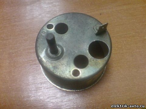
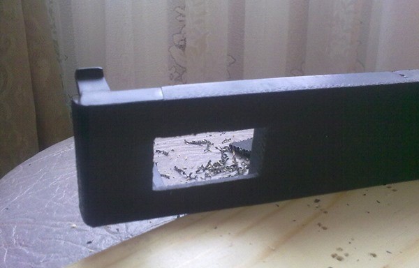
I don’t remember where this measuring head came from, but I always thought it was “killed to zero” - I was wrong. Upon inspection, it was found to be completely adequate. That's just the appearance...

Disassembled to the maximum. I washed the body and glued the top part. I scraped off the extra zeros from the scale with the tip of the blade of a small stationery knife. The result is a 15 volt scale. Instead of 150k resistance, I soldered a jumper into the block. The broken tip of the arrow was returned to its place using a piece of insulation and glue.
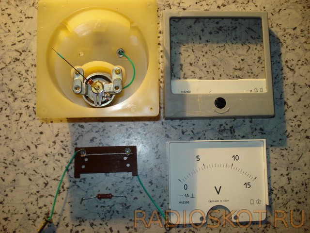
The arrow, of course, needed balancing. I used the following technology to balance the arrows with existing counterweights with droplets of solder on them (move with a well-heated soldering iron, these same droplets).
- Where to move- place the arrow horizontally and see what outweighs, if the arrow, then move the drop from the center. If there is a counterweight, then the drop is towards the center.
- Which drop should I move?- place the arrow vertically.
- a) you need to move “towards the center”. The arrow has deviated to the right - we move the right drop. Left - left.
- b) you need to move “from the center”. The arrow deviates to the right - move the left drop. Left - right.
I filled the existing recesses in the upper part of the body with plastic using a soldering iron and leveled it with a file, then with fine sandpaper and then with the finest sandpaper, finally painted it and inserted the cut glass into it with glue. I also painted the inner metal strip (so that everything was the same color), dried it and assembled it.
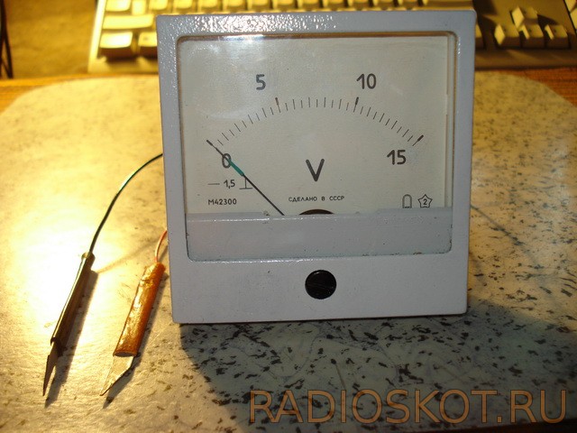
External charm appeared. And to add technical sophistication, I added a three-position switch and three resistors to the measuring head.

The measuring head became the owner of three measurement limits: 3, 15 and 30 volts. Here's a picture printed circuit board and part-time schemes:

I'll stop at the moment of assembly. As it turned out, learning to dig out the compound from the gap between the lower and upper parts of the measuring heads and thereby separating them is not a problem, the problem is connecting them. Well, don’t really bother filling them with compound again. I connect like this:
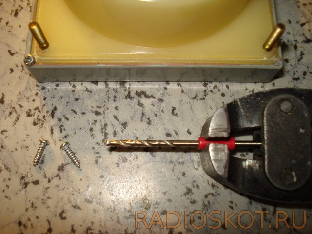
In the very corner I drill a hole with a slightly smaller diameter than the prepared self-tapping screws (exclusively aluminum) and... And if anyone is bothered by the possibility of dust getting inside, then there is plasticine for this. When the meter was ready (he called it a first-level voltmeter), he instructed those involved and gave it to them for use. I liked the device, especially because there is only one “button”. I asked him not to push the probes into the socket - it’s better to just use the nails. With wishes of success, Babay.
Discuss the article DIGITAL VOLTMETER