The main parameters of the AC circuit. Alternating current. main parameters
Alternating currentcall this electricity, which periodically changes in magnitude and direction.
To obtain alternating current, electric machine generators are used, the operation of which is based on the phenomenon electromagnetic induction... Alternating current has a huge practical significance... Almost all electricity is generated as AC power.
The ability to receive alternating current different voltages (high - for the transmission of energy over long distances, low - for powering various consumers), the simplicity of the device of alternators and motors, their reliability, ease of use and high specifications
gave them widespread use.
The most widespread is the sinusoidal current. The change in the current according to the sinusoidal law occurs smoothly, without surges and sharp drops, which has a beneficial effect on the work electric cars and devices.
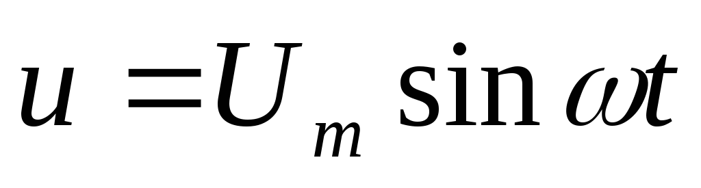
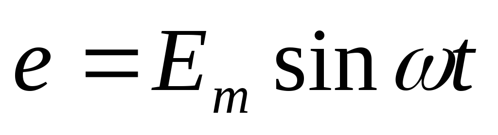
The timing diagram of the sinusoidal current is shown in Fig. 1. Its instantaneous value is described by the formula
Where is the maximum value (amplitude) of the current; - angular frequency;
Initial phase (the value of the argument at the initial moment of time, that is, at t \u003d 0).
Variable EMF, aC voltage and alternating current are characterized by period, frequency, instantaneous, maximum values, rms value.
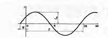
Figure: .1. Timing diagram of sinusoidal current
Period. The time during which the variable EMF (voltage or current) makes one complete change in magnitude and direction (one cycle) is called a period. The period is indicated by the letter T and is measured in seconds (s).
Frequency... The number of complete changes in the variable EMF (voltage or current), made in 1 s, is called the frequency. Frequency is designated by a letter and is measured in hertz (Hz). When measuring high frequencies, the units of kilohertz (kHz) and megahertz (MHz) are used:
1 kHz \u003d 1 OOO Hz, 1 MHz \u003d 1 OOO kHz \u003d 1 OOO Hz.
The higher the AC frequency, the shorter the period. Thus, frequency is the reciprocal of the period:
When a loop rotates in a magnetic field, one loop of it corresponds to 360 °, or 2n radians. The angular velocity of rotation of this loop is expressed in radians per second (rad / s) and is determined by the ratio. This quantity is called the angular frequency and is denoted by the letter:
![]()
The angular frequency of the current, expressed in radians per second, is times greater than the frequency of the current, expressed in hertz
Instantaneous and maximum values... The values \u200b\u200bof the variable EMF, current strength, voltage and power at any time are called instantaneous values these values \u200b\u200bare designated respectively by lowercase letters (,,,) and written as follows:
Receiving single-phase alternating current. Basic parameters of alternating current.
A variable is a current whose change in value and direction is repeated at regular intervals.
Let's consider the principle of operation of the simplest alternator. Between the poles of an electromagnet or a permanent magnet (Fig. 1) there is a cylindrical rotor (armature) made of electrical steel sheets. A coil is mounted on the rotor, consisting of a certain number of turns of wire. The ends of this coil are connected to slip rings that rotate with the rotor. Fixed contacts (brushes) are connected to the slip rings, with the help of which the coil is connected to the external circuit. The air gap between the poles and the rotor is profiled so that the induction magnetic field in it it changed according to a sinusoidal law:
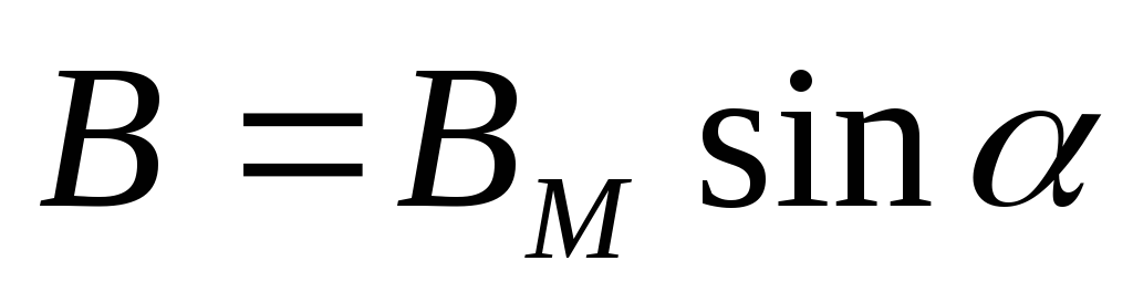
where  - the angle between the plane of the coil and the neutral plane
  .
.
When the rotor rotates in a magnetic field at a speed  induction EMF is induced in the active sides of the coil
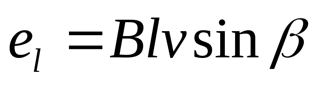

where  - the angle between the direction
yami induction vectors magnet
foot field INand speed v;
l- the length of the active sides of the coil turns.
The magnetic field in the gap is located so that the angle 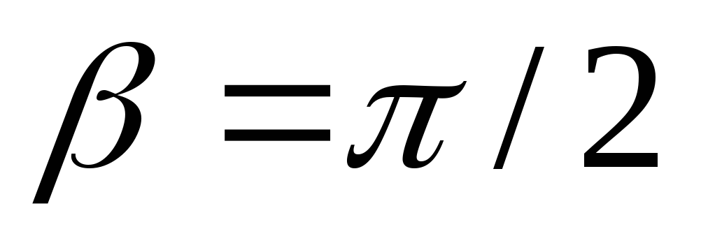 ... In this way,
With the number of turns the number of active sides of the coil is  ... Then the EMF of the coil:, where
  - the maximum value of the EMF.
Thus, the EMF of the generator changes according to a sinusoidal law. If a load is connected to the generator terminals, then a current will flow through it, which will also change according to a sinusoidal law.
The following parameters are used to quantitatively characterize the alternating current.
1. Instant valuescurrent i, voltage u, EMF e- their values \u200b\u200bat any time: 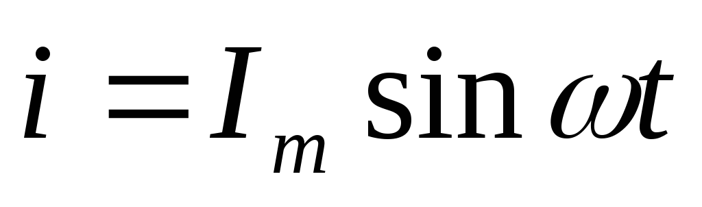 ;
; ;
; .
.
2. Amplitude valuescurrent 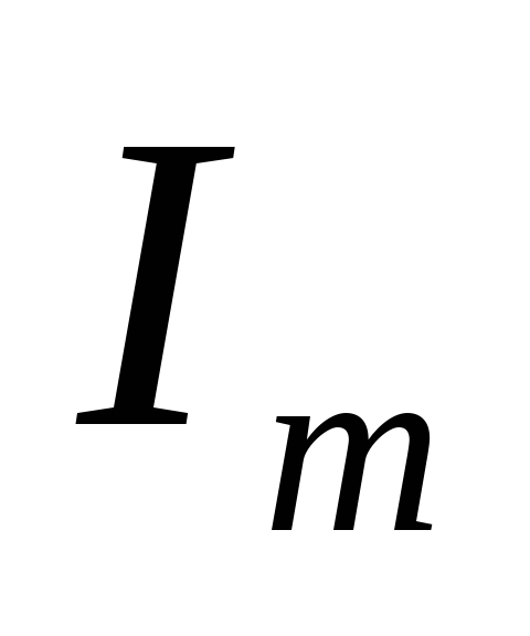 , voltage
 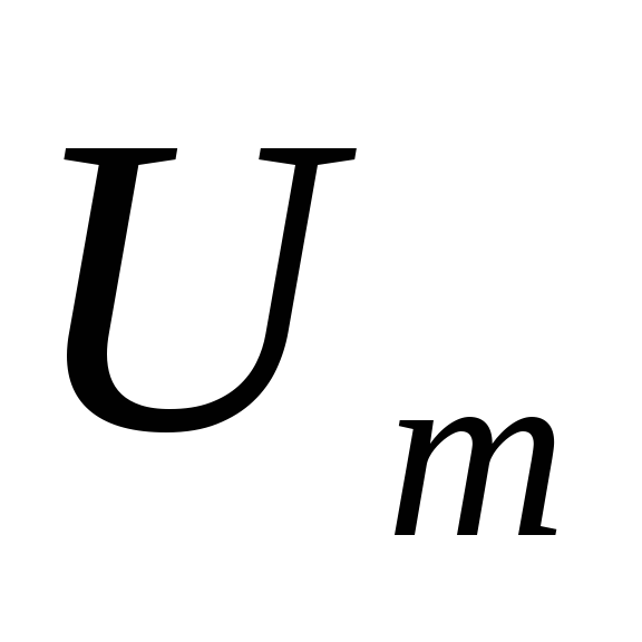 , EMF
, EMF  - maximum values \u200b\u200bof instantaneous values I,
uand
e(see pic)
- maximum values \u200b\u200bof instantaneous values I,
uand
e(see pic)
3. PeriodT- the period of time during which the current makes a full oscillation and takes the same instantaneous value and sign.
4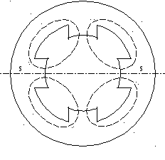 .Angular velocity characterizes the speed of rotation of the generator coil in a magnetic field. In practice, to obtain the desired frequency at a relatively low angular velocity, generators have several pairs of poles r.
The figure shows a generator with two pairs of poles, in which, in one revolution of the coil, the EMF changes position 4 times or 2 rtime. Let's introduce the concept of electric angle  e-mail :
email \u003d
e-mail :
email \u003d  ... Then the speed determines the electric angular velocity of the coil:
 email / ( pT) \u003d p2
  / (pT) \u003d 2 / T,
where p2 - electric angle corresponding to one revolution of the coil in space; pT- time corresponding rperiods of current.
Thus, this formula determines the electrical speed.
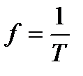
5. Cyclic frequencyfIs the reciprocal of the period T,those. f=1/ T,
and characterizing the number of complete current fluctuations in 1 s.
The unit for cyclic frequency is hertz (Hz):
[f]=1/c\u003d Hz.
6. RMS current valuesI, voltageU and EMF E.To measure alternating current, voltage and EMF, the concept of effective value is introduced. Alternating current is compared with constant thermal effect. If the position of the rheostats is chosen so that the amount of heat released in the circuits (see Fig.) On the resistor R is the same, then we can assume that the currents in the circuits are the same.
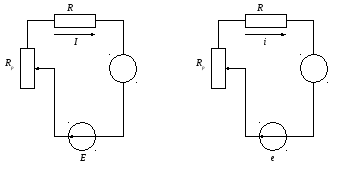

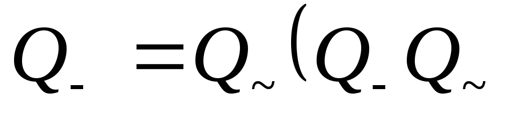
Let's find the relationship between the effective and peak current value. By definition ,
 - the amount of heat released by direct and alternating currents):
 ,
,
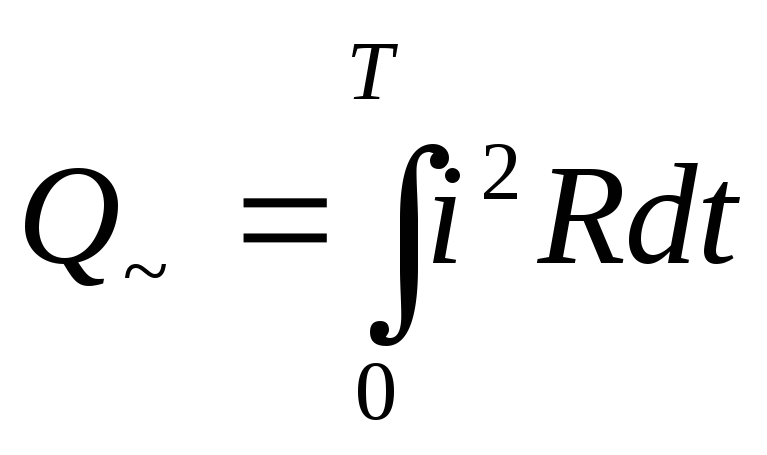
where i 2 Rdt - quantity of heat , alternating current emitted over time dt.
Equating these expressions, we get: 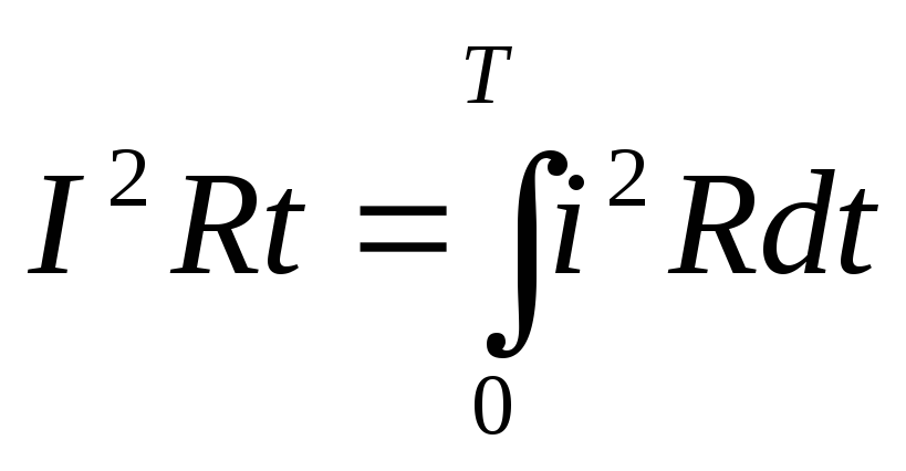 .
.
By reducing by a common factor Rand considering that 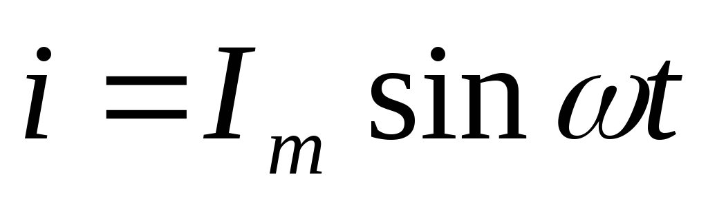 , we find an expression for the effective value of the current:
 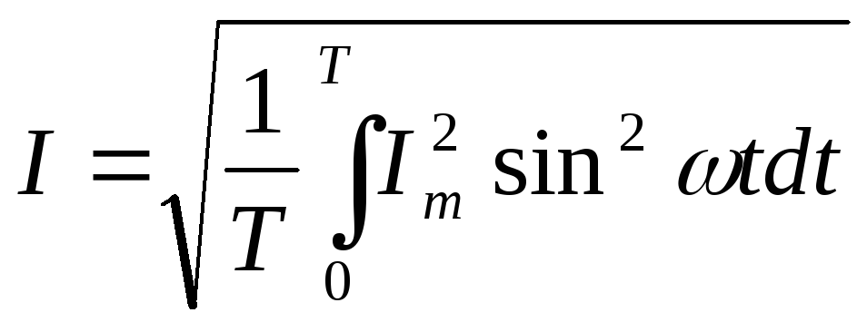 ,
,
or after integration: 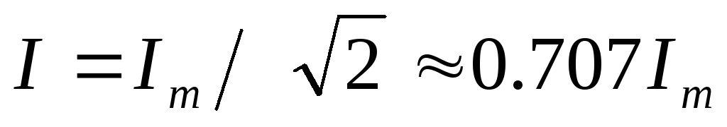
It is widely used in industry and in everyday life sinusoidal variable current. The name "sinusoidal current" is explained by the fact that the voltage and current in the circuit change according to the sine law. Often such a current is called simply alternating or simply sinusoidal.
The advantages of alternating current are as follows:
1. AC motors are simpler, cheaper and more reliable than DC motors. This is very important because millions of electric motors are used in industry and in everyday life.
2. Alternating current can be transformed, ie, using a transformer, increase or decrease its value.
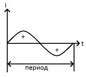
Figure: 40. A circuit of sinusoidal alternating current and a graph of sinusoidal current
A circuit with an AC source and a graph of AC variation is shown in Fig. 40. The figure shows a sinusoidal variable current ... The graph will look exactly the same. sinusoidal voltage or EMF.
Unlike direct current, alternating current constantly changes in magnitude and direction.
Sinusoidal oscillations consist of two half-periods - positive and negative. Figure 40 shows that the half periods of the sinusoid are the same in height and width. They differ only in polarity.
When the half-cycle is changed, the polarity of the voltage at the source terminals and, accordingly, the direction of the current in the circuit (see Fig. 40).
From an examination of the sinusoid graph, it can be seen that the value of the alternating current in the circuit is constantly changing. At the initial moment of the period, the current is zero. Then the current increases to a positive maximum, after which it begins to decrease and drops to zero. At this moment, the first (positive) half-period ends.
In the second (negative) half-cycle, the current rises again to a maximum, but its direction (polarity) is opposite to what it was in the first half-cycle. Then the current drops to zero and the second half cycle ends.
After that, the considered process of changing the magnitude and direction of the current is repeated.
Receiving alternating current
Alternating current used in industry and in everyday life is generated by generators in power plants. The work of generators is based on the phenomenon of electromagnetic induction. To better understand the principle of the generator, repeat the phenomenon of electromagnetic induction. Let's consider how the generator works. In the generator, in a magnetic field, a frame rotates with an angular velocity ω (omega). The magnetic field is generated by electromagnets not shown in the figure. The frame is a bent rectangular conductor. The rotation of the frame is provided by some kind of external force. For example, in a hydroelectric power plant, the rotation of the frame is provided by falling water.
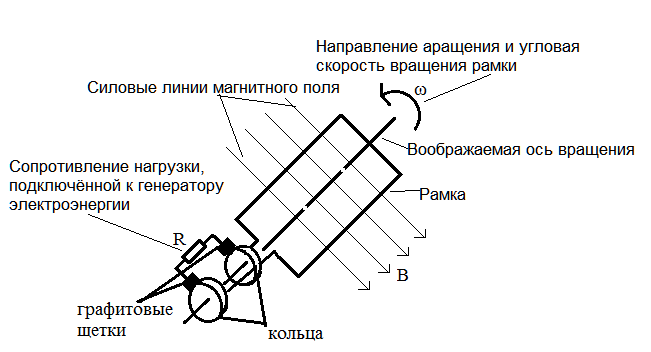
Figure: 41. The principle of operation of the alternator
The sides of the frame cross lines of force magnetic field. In this case, an EMF is induced in the frame, in accordance with the phenomenon of electromagnetic induction.
Each end of the frame is connected to a copper ring that rotates with the frame. Graphite brushes are pressed to the rings. Rings and brushes are needed to transfer the EMF induced in the rotating frame to the stationary load resistance R n.
Alternating current generators are found not only in hydroelectric power plants. Alternators in cars and other devices have a similar design and principle of operation.
Note that if necessary d.C., then it is obtained from a variable by straightening it.
AC parameters
Alternating current is characterized by a number of parameters. Let's consider the most important of them.
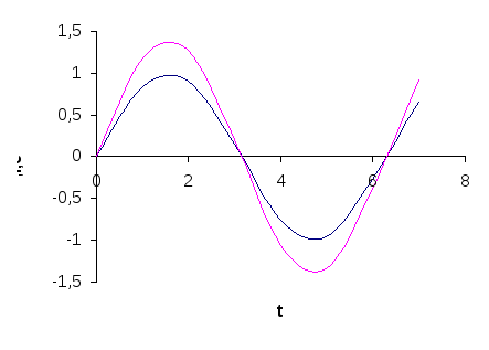
In fig. 42 shows a graph of sinusoidal current. The graphs of sinusoidal voltage or EMF look similar.
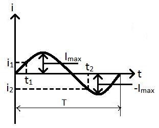
Figure: 42. Graph of sinusoidal current. The period of the sinusoid T.
Shown instant i and amplitude I m values \u200b\u200bof sinusoidal magnitude
1. Period - the time during which the sinusoid makes one complete oscillation. Period T measured in seconds.
2. Frequency - shows the number of oscillations of a sinusoid in 1 second. The frequency is indicated by the letter f (eff) and is measured in hertz (Hz). The frequency of the sinusoidal current used in industry and in everyday life is 50 Hz. Frequency and period are related by the formula:
3. Angular frequency ω (omega) - shows the angular speed of rotation of the generator frame (angle, in radians, by which the generator frame will rotate in one second):
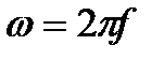
One full rotation of the frame is 360 degrees, or 2π radians.
4. Instantaneous value of current, voltage or EMF. It is denoted by a small (lowercase) letter: i, u, e.
Instantaneous is the value of a sinusoidal value at a given moment of time, for example, at t 1, the value of the current is i 1. Fig. 42 shows the instantaneous values \u200b\u200bof the current for two moments of time. It can be seen that at each moment of time the current has its own value. Compare in the figure the magnitude (instantaneous value) of the current at times t 1 and t 2.
5. Amplitude (maximum) value current, voltage or EMF - the largest of all instantaneous values.
In fig. 42 shows the peak (maximum) current values \u200b\u200bfor positive I m and negative -I m half-periods. They are the same in size.
Amplitude values \u200b\u200bare indicated by a capital letter with the index m. Sometimes, instead of the letter m, max is written.
6. RMS value of current, voltage or EMF. It is designated by a capital letter without an index: I, U, E.
Acting is the most important for practice. It is used most often to estimate the magnitude of an alternating current. Voltmeters and ammeters show exactly effective value, respectively voltage or current.
In a standard household network, the effective voltage is 220 V.
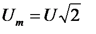
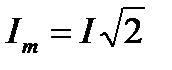
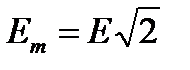
The amplitude value is 1.41 times greater than the acting value (root of two).