Primary and secondary transformer winding diagram. Electric cars
Bookmark this site
In a first approximation, the effect of the secondary current i2 on the primary circuit of the transformer can be described as follows.
The current i2, passing through the secondary winding, tends to create a magnetic flux in the transformer core, determined by the magnetizing force (HC) i2w2. According to Lenz's principle, this flow should have a direction opposite to the direction of the main flow. Otherwise, we can say that the secondary current tends to weaken the magnetic flux that induces it. However, such a decrease in the main magnetic flux Ф т would violate the electrical equilibrium:
u 1 \u003d (-e 1) + i1r1,
since e1 is proportional to the magnetic flux.
A predominance of the primary voltage U1 is created, therefore, simultaneously with the appearance of the secondary current, the primary current increases, moreover, so much as to compensate for the demagnetizing effect of the secondary current and, thus, maintain electrical equilibrium. Consequently, any change in the secondary current should cause a corresponding change in the primary current, while the secondary winding current, due to the relatively small value of the component i1r1, has almost no effect on the amplitude and nature of changes in time in the main magnetic flux of the transformer. Therefore, the amplitude of this flux Ф t can be considered practically constant. This constancy of Ft is characteristic of the transformer mode, in which the voltage U1 is kept constant, applied to the terminals primary winding.
The operation of the transformer is based on the phenomenon of mutual induction. The electromotive force of mutual induction arises in one of the two coils (Figure 1), for example, in coil 2, when a current flows in the other 1, creating an alternating magnetic flux Ф 0. When the magnetic flux changes power lines magnetic fieldarising around the coil 1, penetrate into another coil and cross its turns. As a result of this, an electromotive force (emf) is created in the coil 2, which is electromotive force mutual induction.
1 - coil (winding) primary circuit; 2 - coil of the secondary circuit; 3 - rheostat for changing the current in the primary circuit
Figure 1 - Magnetic coupling of two coils streamlined by alternating current
If the ends of the coil 2 are connected to some receiver of electrical energy, then the emf of the mutual induction creates a current in it, that is, it transfers some energy to it. The coil 2 receives this energy with the help of the magnetic field created by the current of the first coil, and the current source immediately replenishes this energy. So, on the basis of electromagnetic communication, the energy of the source is transferred from one coil to another.
The current flowing in the first coil and creating a magnetic field around it is called exciting or primary and is designated I1. An electrical circuit made up of a current source, connecting wires and coil 1 is called primary. The alternating magnetic field crosses not only the turns ω2 of the coil 2, but also the turns ω1 of the coil 1. Therefore, the self-induction emf E1 arises in the primary coil.
The electromotive force of mutual induction arising in the coil 2 is called secondary and denoted by E2; electrical circuitconnected to this coil is also called secondary. The current flowing in the secondary circuit is called secondary and denoted I 2 (Figure 2, a, b).
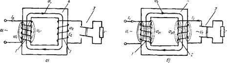
a - mode idle move; b - load mode; 1 - primary winding; 2 - secondary winding, 3 - switch; 4 - magnetic circuit
Figure 2 - Primary and secondary windings on the magnetic circuit
The magnetic flux, crossing any closed loop (for example, a winding turn), creates an emf and current in it. According to Lenz's rule, this current (for example, the secondary current I 2) is directed in such a way that, by its magnetic action, it interferes with the cause that caused it.
The intensity of the magnetic field, that is, the magnetic induction, is proportional to the current, depends on the number of turns of the primary winding and the properties of the medium (on the magnetic permeability) in which the turns are located. For ferromagnetic substances, such as steel, the magnetic permeability is many times greater than the magnetic permeability of air. Therefore, to enhance the magnetic field created by the primary current, groups of series-connected turns, i.e., the winding coils, are placed on a magnetic circuit made of special electrical steel plates. A set of plates made of electrical steel, assembled in such a geometric shape that allows localizing the main part of the magnetic field in it, constitutes the magnetic system, or the magnetic circuit of the transformer. The core is the part of the magnetic circuit on which or around which the winding coils are located.
Due to the high magnetic permeability of steel, the magnetic core enhances the magnetic field of the current, increases the magnetic flux Ф 0 and emf E2 (Figure 2, a). At no-load, when the current flows through the winding connected to the power source, and there is no current in the other winding (the load is not turned on), the power consumed from the network is spent only on creating a flux Ф 0, i.e. on magnetizing the magnetic circuit and induction voltage at the open terminals of the winding 2. The flux Ф 0, which is completely coupled with all turns of windings 1 and 2, is called the main or main current, and the primary current I1 at no-load is called the no-load current of the transformer. The no-load current is usually denoted by I0.
As you know, the magnetic flux induces an emf, which creates a current not only in the winding, but also in the steel of the magnetic circuit. The current generated by the emf flows in a closed loop (vortex motion) in the core in the direction perpendicular to the magnetic flux (Figure 3, a).
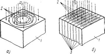
a - solid; b - laminated; 1 - magnetic circuit; 2 - eddy currents; 3 - layers (plates) of the magnetic circuit
Figure 3 - Eddy currents in the magnetic circuit
A magnetic circuit can always be imagined as consisting of a large number of cylindrical layers forming similar closed contours in cross-section. The set of currents flowing along all these circuits forms eddy currents of the magnetic circuit; due to electrical resistance steel, they cause heating in it and loss of power coming from the source.
If the magnetic circuit is made of solid steel, then its resistance will be small and eddy currents can reach large values... To reduce the magnitude of eddy currents (they cannot be completely eliminated), the magnetic core is assembled from separate insulated steel sheets.
Indeed, in order to reduce eddy currents, it is necessary to reduce the emf arising in the magnetic circuit and increase the resistance. In this case, the thinner the sheet, the less the elementary emf that creates the current, the smaller the cross section, i.e. more resistance, the current is less (Figure 3, b). As can be seen from the figure, the eddy currents 2 that arise in the circuits are closed only in each individual plate, and not throughout the entire magnetic circuit.
Due to the small magnitude of the emf, as well as an increase in the resistance of the circuit, the cross section of which has become much smaller than that of a solid magnetic circuit, the eddy currents are small. To make them even smaller, silicon is added to the steel used for the manufacture of the magnetic circuit, which significantly increases the resistivity without deteriorating at the same time its magnetic properties. In addition, the properties of steel depend on the method of its manufacture. In particular, the method of rolling steel plays an important role. Hot-rolled steel has significantly higher specific losses than cold-rolled steel. Considering that the specific losses from eddy currents are proportional to the square of the thickness of the steel sheet, now instead of the thickness of 0.5 mm, steel with a thickness of 0.33-0.35 mm and even 0.28 mm is increasingly used.
However, eddy currents are not the only cause of losses in the magnetic circuit. Another reason is the reversal of the magnetization of steel due to a continuous change in the magnitude and direction of the alternating current. And since the change in the magnetic field is directly related to the change in the direction and magnitude of the current, the steel of the magnetic circuit is continuously magnetized and demagnetized.
It is known that the magnetization curve, i.e., the dependence of the magnetic induction on the magnitude and direction of the current, forms a so-called hysteresis loop (Figure 4). Continuous magnetization reversal is accompanied by heating of the steel, i.e. energy losses. The area covered by the hysteresis loop is proportional to the specific power loss spent on magnetization. These losses are called hysteresis losses or magnetization reversal losses. To reduce them, steel with a low carbon content and other additives that improve its properties are used.
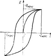
Figure 4 - Hysteresis loop - the dependence of the induction B on the change in the magnetizing currentI
The losses considered by us arising in the magnetic system of the transformer at rated voltage on the primary winding and rated frequencyare called magnetic losses.
Chapter III
TRANSFORMERS
§ 3.1. GENERAL INFORMATION
The device of transformers. A transformer is a static electromagnetic AC converter.With the help of a transformer in AC systems, it is convenient to change the voltage. Despite the fact that the transformer has no rotating parts, its working process is similar to the processes
Figure: 3.1. Single-phase transformer diagram: a - rod; b - armor: 1 - primary winding; 2 - secondary winding; 3 - rod; 4 - yoke
flowing in other electrical machines, since it is based on the phenomenon electromagnetic induction.
The transformer windings are made in the form of multi-turn cylindrical coils. The winding connected to the supply network is called primary, and the winding to which the load is connected is called secondary. To ensure better mutual induction, the primary and secondary windings of each phase are located as close as possible to each other on a common core (Fig. 3.1), which is a package assembled from sheets of electrical steel.
The cores of power transformers are usually recruited (stacked) from rectangular sheets of electrical steel in such a way that the layers recruited in various ways (Fig. 3.2, andand
6 ), alternated through one (Fig. 3.3, a). The core sheets are pulled together with insulated pins.
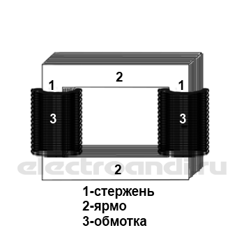
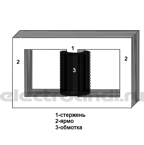
There are two types of cores: rod (Fig. 3.1, and) and armor (Fig. 3.1, b). The armored core has a branched magnetic system, due to which the flux in the rod 3, on which the winding is located, is greater than the flux in the yoke 4 . Heart-
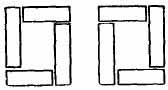
Figure: 3.2. Arrangement of sheets when assembling the transformer core "overlapping"
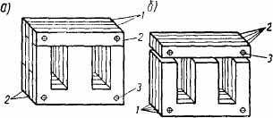
Figure: 3.3. Assembling the magnetic circuit of the transformer: a) overlapping; b) end-to-end: 1 - plates of the W-shaped profile; 2 - rectangular plates; 3 - rod pins
the nicknames of low-power transformers are of W-shaped, U-shaped or toroidal shape. The core package can be assembled with an overlap (Fig. 3.3, a) or butt-joint (Fig. 3.3, b). The first
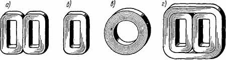
Figure: 3.4. Ribbon cores: a - armored; b - core; в - toroidal; g - three-phase
the method should be given preference, since in this case in the magnetic circuit creates smaller gaps.
IN recent times cores made from a narrow strip of electrical steel are spreading (Figure 3.4). In most cases, tape cores are cut into two halves (Figure 3.5) so that spools can be put on them. After that, the cores are pulled together and fixed in a tightened form (Fig. 3.6).
The transformer windings can be arranged concentrically one inside the other or in alternating order along the height of the core of the magnetic circuit, in the latter case, the primary and secondary windings are made in the form of disk coils.
In low-power transformers, a multilayer winding is used, which is wound continuously along the entire length of the magnetic core until a given number of turns is obtained. In some cases, the winding is made of separate parts, wound on independent frames. Each such part of the winding is a complete structural part, called a biscuit. The biscuits are put on the core of the magnetic circuit along its entire height and are electrically connected to each other in one way or another. In fig. 3.7 shows the device of a single-phase tapered transformer with a tape core.
Transformers can have several secondary windings (two, three or more). In fig. 3.9, bshown a diagram of the star-connected windings three phase transformer... Winding A 1 B 1 C 1 primary, A 2 B 2 C 2 -secondary.
According to the cooling method, transformers are divided into oil (the windings of which are immersed in oil) and dry (air-cooled).
Our factories produce transformers with power ranging from fractions of a volt-ampere and voltage from one volt to hundreds and
Figure: 3.5. Slit ribbon core
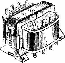
Figure: 3.6. General view of an armored transformer with a tape core
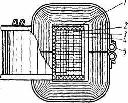
Figure: 3.7. The device of a single-phase transformer with a capacity of 30 tue: 1 - frame; 2 - primary winding; 3 and 4 - secondary windings; 5 - clamping clamp
thousand kilovolt-amperes and a voltage of hundreds of kilovolts. Depending on the application, different requirements are imposed on transformers.
Power transmission transformers are manufactured for a long service life for many decades. On the way from ge-
in a non-irrigating station to the consumer, electrical energy usually undergoes three or even fourfold transformation, so the efficiency of transformers for power transmission should be as high as possible.
Low-power transformers used in automation circuits can have a small efficiency, because the
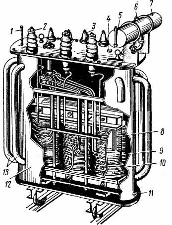
Figure: 3.8. Device of a three-phase transformer with a capacity of 300 kvafor voltage 6 sq:
1 - thermometer; 2 - input of high voltage winding; 3 - winding input low voltage; 4 - plug for filling oil; 5 - oil indicator; 5 - plug for filling oil; 7 - expander; 8 - magnetic circuit; 9 - low voltage winding; 10 - high voltage winding; 11 - oil drain plug; 12 - oil tank; 13 - radiator pipes for oil cooling
the energy is relatively low. These transformers are designed for a significantly shorter service life, since the electronic equipment in the circuits in which they operate wears out relatively quickly.
Transformers for radio electronics must be small in size and low in cost.
Operating principle.When passing electric current a magnetic flux is generated along the transformer windings. It is convenient to consider the flux associated with each winding as consisting of two components: the mutual induction flux and the leakage flux.
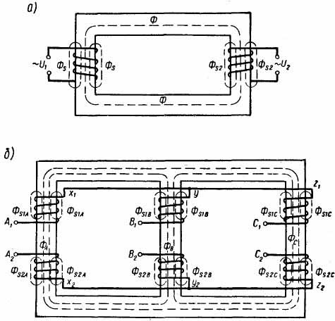
Figure: 3.9. Magnetic flux: a - single-phase transformer; b - three-phase transformer
Mutual induction flux Ф (Fig. 3.9, and) fully adhered to all turns of the windings of the same phase. All other streams are scattering streams. In fig. 3.9, andand bshows the paths of some scattering fluxes Ф S windings. In addition to these paths, there may be others, all of them partially pass through the air.
The primary winding of the transformer is connected to an alternating current supply network. When the secondary winding is open (idle), the primary winding current creates a flux, a significant part of which, coupled with both windings, is the mutual induction flux F.
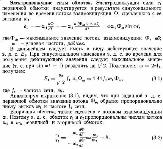
As a result of the time variation of the mutual induction flux in the windings, e is induced. etc. with. Their values \u200b\u200bare proportional to flux linkages, which are equal to the product of the flux of mutual
duction for the number of turns of a given winding. The flux linkage of the primary winding is mainly determined by the supply voltage. It is less than the mains voltage by the amount of voltage drop in the active and inductive resistance of the primary winding.
If the secondary winding of the transformer is short-circuited or to an active-inductive load, then the current of the secondary winding tends to reduce the flux causing it and demagnetizes the core on which the primary winding is wound. As a result, the inductance of the primary winding decreases and its current increases.
In the presence of current in the secondary winding, the magnitude of the mutual induction flux Ф is determined by the joint action of ppm. primary and secondary windings. The magnetizing effect of the increased primary current compensates for the demagnetizing effect of the secondary current, and the mutual induction flux remains almost unchanged. Therefore, e. Remain almost the same as in idle. etc. with. primary and secondary windings. Their values \u200b\u200bcan only change due to an increase in the voltage drop components in the active and inductive resistances of the primary winding.
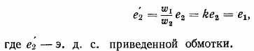
Attitude k called the transformation ratio. This coefficient shows how many times e. etc. with. primary winding more or less e. etc. with. secondary. In some cases, the transformation ratio is defined as the ratio of e. etc. with. windings higher voltage to e. etc. with. low voltage windings.
Taking into account (3.1) and (3.2), we obtain for e. etc. with. secondary winding the following equality:
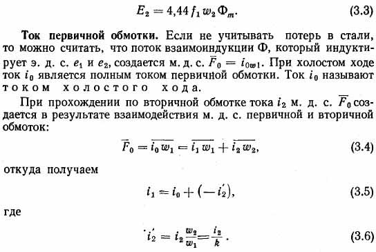
Current i"2 is called the reduced current of the secondary winding. The reduced current should be understood as the secondary current at k= 1.
From (3.5) it follows that when the transformer is loaded, the primary winding current increases in comparison with the no-load current i 0 by the reciprocal of the reduced current i "2secondary winding.
At no-load, the secondary winding of the transformer is open, but in a real transformer in the steel magnetic circuit there are always some secondary closed current loops that act on the primary winding in the same way as the closed secondary winding. The secondary circuits include eddy current circuits in sheets of steel, in tie bolts, etc. These circuits pass along the surface areas of steel that have high resistance, therefore the losses they create are significant, and in the primary winding they mainly cause an active component of the current idle move i 0. Full active component i r no-load current also takes into account losses in steel by
magnetization reversal. Taking into account the active component, the no-load current
where i μ is the magnetizing current required to create a mutual induction flux F.
Thus, taking into account expression (3.5), we can assume that the primary winding current i 1 has two components, one of which ( i 0) creates a mutual induction flux and compensates for losses in steel during no-load, and the other (- i"2) compensates for the demagnetizing effect of the secondary winding current.
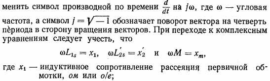
Systems of differential equations. According to the second Kirchhoff's law for the voltage of the primary and secondary windings of the transformer phase, the following equations can be drawn up:
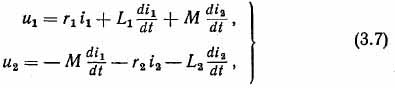
where and- instantaneous voltage value at the winding terminals; i - instantaneous value of winding currents;
r- active resistance of the windings;
L- inductance corresponding to the total flux coupled to the winding;
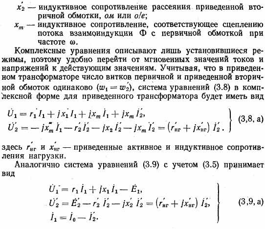
M- mutual inductance between the windings, determined by the coupling of the flow Ф with the turns of the primary and secondary windings:
Index 1 refers to the primary winding, index 2 - to the secondary.
If the flux coupled with the primary winding (Fig. 3.9) is considered as consisting of two parts (the mutual induction flux Ф and the scattering flux Ф s), then the total inductance of the primary
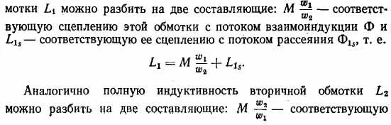
coupling of the secondary winding with the mutual induction flux Ф and L 2s- corresponding to its adhesion to the scattering flux, i.e.
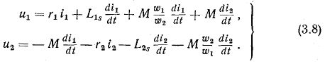
Then the system of equations (3.7) takes the form
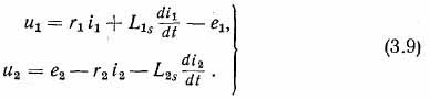
As a result of the interaction of m. the primary and secondary windings create a mutual induction flux F. Its coupling with the turns ω 1determines e. etc. with. primary winding:
Coupling of the flow Ф with turns ω 2determines e. etc. with. secondary winding:
therefore, from expression (3.8), we have the following system of equations
Equilibrium equation m.d.s. (3.4) and the voltage equations for the primary and secondary windings constitute the system of equations for the transformer.Using any of the systems of equations (3.7), (3.8) or (3.9), you can analyze the processes occurring in the transformer. The system of equations (3.7) is usually used in electrical engineering and in the analysis of transient processes. Systems of equations (3.8) and (3.9) are widely used in the theory electric cars... In what follows, we will mainly use systems of the type (3.8) and (3.9).
Reduced transformer.To facilitate the analysis of the processes occurring in the transformer, to simplify the vector diagram and the possibility of constructing an equivalent circuit, it is conventionally assumed that the reduced current of the secondary winding i"2 is its actual current. For this purpose, the actual secondary winding with the number of turns ω 2 conditionally replaced by a dummy winding,
with the number of turns ω 1... Such a conventional winding is called the reduced secondary winding, and the replacement operation is called the reduction of the secondary winding to the primary one.
Since the number of turns of the reduced secondary winding is equal to the number of turns of the primary, then the electromotive forces of both windings induced by the mutual induction flux are equal, i.e.
It is necessary that the reduced winding be equivalent to the actual secondary winding. Therefore, losses should remain:
In the given winding, the same relationships between the active and inductive voltage drops must be preserved that exist in the actual winding. From here we obtain an expression for the inductive resistance of the reduced winding
Knowing the given values \u200b\u200bof current, voltage and resistance, it is always possible to determine their actual values \u200b\u200bby recalculation and, conversely, knowing the actual values, to determine the reduced ones.
Systems of equations for the reduced transformer in the steady state.In the case of a sinusoidal change in the currents and voltages of a transformer, when considering steady-state processes, one can go from a system of differential equations to a system of equations in a complex form. To formally obtain complex equations, it is sufficient in differential equations to
Substitution schemes. In the theory of electrical machines, equivalent circuits are widely used, in the transition to which actual transformer connections, i.e. electromagnetic ones, are replaced by electrical ones.The circuits are designed in such a way that their currents and voltages are described by the same equations as in the transformer. The transmitted power, phase relationships of currents and voltages in the equivalent circuit are the same as in the transformer.
Replacement circuits are convenient for analytical and experimental research of steady-state and transient processes. They can be easily assembled from separate inductive and active resistances. The voltages and currents of all sections of the circuit are easy to calculate or measure. In the case of a polyphase transformer, the equivalent circuits are drawn up for one phase.
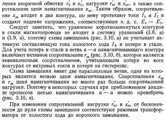
Systems of equations (3.8, and) and (3.9, and) corresponds to the equivalent circuit shown in Fig. 3.10, and.Each term of the equation of the system, reflecting the voltage drop or e. etc. with. winding corresponds to a certain section of the circuit, on which there is a voltage drop in a given resistance or an applied voltage acts. Arrows in the equivalent circuit show the positive direction of the currents of the primary and secondary windings.
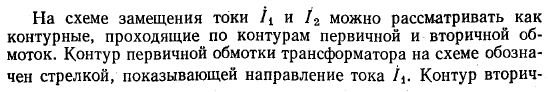
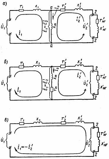
Figure: 3.10. Transformer equivalent circuit: a - excluding active resistance in the magnetizing circuit; b - taking into account the active resistance in the magnetizing circuit; c - excluding the magnetizing circuit
1. Why with an increase in the current in the secondary winding of the transformer increases the current in the primary winding? How does the flow of mutual induction and the eduction induced by it change? d. with? Why the transformer cannot work from the mains direct current?
2. What determines the magnetic flux in the transformer core? If we consider the remaining quantities unchanged, then how will the flux change with an increase in the primary voltage, the section of the magnetic circuit, the number of turns of the primary winding, the number of turns of the secondary winding, the frequency of the network? Why doesn't the flux change when the cross section of the magnetic circuit changes? What does this change?
3. In what case will the measured current of the secondary winding be equal to its reduced current? What is a Reduced Transformer? Does the number of turns of the secondary winding affect the reduced value of its e. d. with?
4. How e are taken into account in the equations of the transformer. etc., induced by scattering flows? How are the leakage fluxes of the transformer windings closed?
4.1 The device and principle of operation of the transformer
Transformers are devices designed to convert voltage or current (Fig. 28). The value of such a device is determined by the extremely wide range of situations in which it is used. Thanks to transformers, electrical energy acquires such forms, parameters and properties that are most in demand and convenient for specific applications. It should, however, be remembered that transformers can only work in AC circuits and their inclusion in DC circuits of even a small voltage can damage them.
The simplest (to demonstrate the principle of operation, but not by design) transformer consists of three elements or nodes: 1) primary winding; 2) magnetic circuit; 3) secondary winding (fig. 29)
Both transformer windings are electrically isolated from each other and from the magnetic circuit. The latter is a massive ferromagnetic core that creates a magnetic connection between the windings. The electrical energy entering the primary winding is converted by it into magnetic energy, which is transmitted through the magnetic circuit to the secondary winding with subsequent transformation back into electrical energy, but already the secondary winding. Part of the energy in the conversion process is lost in the transformer, causing it to heat up. The ratio of the share of transmitted energy to that taken from the primary source determines Transformer efficiency and is calculated by the formula, where W 1 is the energy supplied to the primary winding; W 2 - energy supplied to the consumer from the secondary winding.
The efficiency of modern transformers reaches 99%, which indicates the extreme efficiency of these devices as power transmitters.
Operating principle transformer is based on the law of electromagnetic induction (EMI). Recall that in the physical sense, it is a phenomenon generation of a vortex by an alternating magnetic field electric field. Mathematically, this law is given by the well-known formula for the EMF of a vortex electric field:
where ΔF is the change in magnetic flux over time Δt. Therefore, in modulus, EMF is equal to the rate of change of the magnetic flux. This, in turn, means the presence of a phase shift between F and e by 90 0 (this fact is true for any value and its speed). The minus sign means that the EMF is out of phase from the magnetic flux. The EMF itself, physically, arises at any loop that envelops the changing magnetic field (in Fig. 30 - at 3 loops), and its direction depends on the increase or decrease of the magnetic field.
 Consider how the transformer works.
When serving alternating voltage to the primary winding, alternating current... In turn, the alternating current creates an alternating magnetic field around itself. Since, technologically, the primary winding is a coil, its magnetic field is concentrated inside it (outside of it, the magnetic fields of the different sections of the turns are subtracted). Sl-
the magnetic field of the primary winding, falling into the magnetic circuit passing through it, is repeatedly (hundreds and thousands of times) amplified by its own magnetic field and closed through its circuit. As a result, a significant variable magnetic flux begins to circulate through the magnetic circuit F. In accordance with the EMP law, a vortex EMF occurs in any section of the magnetic circuit. This EMF arises everywhere in the surrounding space and enters both the primary winding, the secondary, and the magnetic circuit.
In the primary winding, it turns out to be completely antiphase to the mains voltage, since, as already mentioned in the previous sections, the current in the winding lags behind the voltage by 90 0, and the EMF of the vortex field, in turn, lags behind the current (or what is the same - from the magnetic flux ) by another 90 0. As a result, two electric fields are encountered in the primary winding, directed opposite to each other. The result of this opposition is a small value of the input current (at no load) and a large inductive resistance of the winding. In addition, all coils and windings are usually made of copper, which has a very low ohmic resistance. Hence follows an important quantitative fact - the voltage drop ( u) at each turn occurs only due to the vortex EMF and, therefore, it is numerically equal to this EMF:
![]()
Here it is taken into account that the voltage on the primary winding is evenly distributed on its turns, due to the uniformity of the magnetic flux along the magnetic circuit.
In the magnetic core, the EMF of a vortex electric field creates eddy currents ( foucault currents), which, if no measures are taken, greatly reduce the efficiency of the transformer and cause significant heating and even overheating of the magnetic circuit. To create resistance to such currents, it is assembled from thin plates coated with insulating varnish. This allows to drastically reduce the thermal dissipation of electromagnetic energy and increase the efficiency. Finally, in the secondary winding, the vortex electric field induces its own EMF in each turn, which, adding up on all turns, goes to its terminals in the form of voltage, where N 2 is the number of its turns.
Since we expressed the EMF of the vortex field itself in terms of the mains voltage drop on the primary winding, having made the corresponding replacement in the last formula, we come to the basic form of the transformer:
It follows from it that when the ratio between the number of turns on the secondary and primary windings changes, we can change the ratio between their voltages. Namely: if N 2< N 1 , то U 2 < U 1 - напряжение на вторичной обмотке оказывается пониженным; если N 2 > N 1, then U 2\u003e U 1 - then increased. In the first case, we get a step-down transformer, in the second - a step-up
To determine the degree of voltage transformation, a coef fits and enttransformations and k is introduced:
The transformation ratio, along with the values \u200b\u200bof the voltages of the windings, rated power and efficiency is an important technological parameter of a transformer.
4.2 Transformer operating modes
Since in the considered classical design of the transformer there are two windings, one of which is closed to the primary source, and the second is free, then two modes of its operation are possible: a) the secondary winding is open - idle mode; b) the secondary winding is closed to the consumer - work mode... These modes have a significant difference, since in the second case an additional magnetic field arises in the magnetic circuit from the secondary winding, which affects all electrical parameters of the transformer. Therefore, these modes of operation are considered separately.
The following should be noted here: since on electrical processes many factors influence in the transformer, their accurate accounting at the cause-and-effect level with the help of a qualitative description turns out to be difficult. Therefore, it is easier to understand the processes taking place in the transformer through abstract concepts. In particular, through vector diagrams.
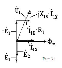
The diagram below (Fig. 31) shows a vector diagram of all parameters of transformers in idle mode. Like any complex diagram, its construction requires mathematical equations connecting all the parameters depicted. For a transformer in idle mode, they are obtained from the Kirchhoff's law:
 1) for primary winding
2) for the secondary winding
Consider the course of constructing such a diagram for idle mode - with the simultaneous clarification of the physical meaning of all the parameters reflected on it.
The construction order is as follows:
1) we postpone horizontally the open-circuit current vector I 1X and the magnetic flux Ф m in the magnetic circuit - parallel to each other. In a vacuum they always oscillate in the same phase; in the magnetic circuit, due to the phenomenon of hysteresis (mismatch of the magnetic field of the current and iron), a slight misphasing is possible, which in this case will be neglected)
2) we postpone with a lag of 90 degrees (down) two vectors of the EMF of the vortex electric field of the EMR - E 1 and E 2. E 1 represents the EMF in the primary winding, E 2 - in the secondary. Obviously, due to the difference in the number of turns in the windings, these EMFs do not coincide in magnitude and are deposited different in length.
3) we postpone the vector - E 1 in the direction opposite to E 1. Its necessity follows from the equation for the voltage of the primary winding. Indeed, it follows from Ohm's law that the mains voltage is opposed by the EMF EMR E 1 (hence the minus sign), the ohmic resistance of the primary winding R 1 (creates a voltage drop I 1 XR 1) and the inductive resistance, x 1, of that part of the magnetic field, which closes on itself bypassing the magnetic circuit (through the air).
4) we postpone the vector I 1 X R 1 from the end of the vector (- E 1) - it must be parallel to the current, since the voltage across the resistor is always in phase with the current.
5) we postpone the vector I 1 X x 1 from the end of the vector I 1 X r 1 - it must be perpendicular to the current, since the voltage on the inductive reactance is always ahead of the current in phase by 90 0
6) we connect the beginning of the vector - E 1 with the end of the vector I 1 X X 1 - the resulting vector will represent the sum of vectors ![]() , i.e. vector U 1.
, i.e. vector U 1.
It can be seen from the plotted diagram that in an accurate representation, the mains voltage exceeds the EMP back-emf. However, in real transformers, this difference is no more than 2-5% due to the smallness of the ohmic and inductive resistance of the primary winding. The voltage across the open secondary winding is exactly equal to E 2. Therefore, with a sufficient degree of accuracy, you can write:
To build a vector diagram in operating mode it is also necessary to draw up the corresponding equations. They will differ from the equations in no-load mode by the form of the equation for the secondary winding. The latter is also obtained from the second Kirchhoff law and has the form ![]() ... It can be seen that the voltage on the secondary winding ( U 2) decreases in comparison with the voltage U 2 at no-load, by the amount of voltage drop in its active and inductive resistances.
... It can be seen that the voltage on the secondary winding ( U 2) decreases in comparison with the voltage U 2 at no-load, by the amount of voltage drop in its active and inductive resistances.
Thus, the following equations are used to build the diagram:
![]()
These equations complicate the diagramming process and, to simplify it, we will neglect internal resistance windings. Then the equations will take a very simple form:
It immediately follows from this type of equations that it is impossible to draw any conclusions about the behavior of the currents in the primary and secondary windings.
In reality, these currents turn out to be closely related for the following reasons. First, it follows from the first equation that, as in the case of no-load, the EMF of the vortex field must be equal and opposite in phase to the mains voltage. Since the voltage of the mains (primary source) is specified and does not depend on the operating mode of the transformer, the magnetic flux in the magnetic circuit of the transformer in operating mode must equal the magnetic flux in idle mode... Meanwhile, in the operating mode, more than one magnetic field circulates in the magnetic circuit - the operating current of the secondary winding creates its own magnetic field.
Secondly, according to Lenz's rule, the secondary winding current must "... have such a direction that the magnetic field created by it tends to compensate for the change in the external magnetic field." In other words, the magnetic field of the secondary winding must be directed against the magnetic field of the primary winding... This allows you to write the general equation for magnetic fluxes in the magnetic circuit - as vectors (!) - in the form:
and taking into account the antiphase nature (in modular form) as:
![]()
Here Ф 0 is the magnetic flux in the transformer, created by the primary winding in idle mode; Ф 1 - magnetic flux of the primary winding in operating mode; Ф 2 - the magnetic flux of the secondary winding.
The meaning of the last equation can be illustrated by the following example. Suppose in the idle mode, the magnetic flux of the magnetic circuit was 20 conventional units (Ф 0 \u003d 20). Then, if the operating current of the secondary winding creates a magnetic flux of 40 cu. (Ф 2 \u003d 40), then the magnetic flux of the primary winding should increase to Ф 1 \u003d Ф 0 + Ф 2 \u003d 40 + 20 \u003d 60 and reduce the total magnetic flux again to 20. This means that between the currents of the primary and secondary windings there is a magnetic communication, and such that an increase in current in the secondary winding entails an increase in current in the primary winding.
The mathematical relationship between currents can be established on the basis of the fundamental law of the theory of magnetism - the law of total current. According to this law, “.. the circulation of the magnetic field strength along a closed circuit is equal to the algebraic sum of currents crossing this circuit. In the adapted version for magnetic circuits with magnetic circuits, it is formulated in the form of an equalization of a magnetic circuit:
Here R M is the magnetic resistance of the transformer magnetic circuit; N is the number of turns with current that encircle the magnetic circuit; I is the current strength in each turn; Ф - magnetic flux in the magnetic circuit. From the formula it follows that:
or, substituting it into the equation for magnetic fluxes, we get:
![]()
or reducing by R M and dividing everything by N 1:
![]()
The last equation establishes the desired relationship between the operating currents in the primary and secondary windings and allows you to build a vector diagram of the operating mode in a simplified form. Let's pre-rewrite it as:
and note in passing that due to the smallness of the no-load current, the second term on the right side of the equation can be neglected; then the connection between the currents in the primary and secondary windings will become especially clear, since the modules are equal, i.e. than more current in the secondary, the greater the current in the primary.
We build the diagram in the following order:
1) 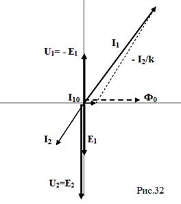 postpone the current ( I 10) and magnetic flux ( F 0) idling mode;
2) put down the EMF of the primary ( E 1) and secondary winding ( E 2); their values \u200b\u200bare determined by the value F 0, N 1, N 2; since EMF of the primary winding is less than that of the secondary, then k<1 и трансформатор повышаю-щий;
3) we postpone the current of the secondary winding ( I 2) - in an arbitrary direction (its direction depends on the nature of the load);
4) in accordance with the equation of currents to the end of the no-load current vector ( I 10) we postpone the vector (- I 2 / k) and construct the sum vector I 1; vector(- I 2 / k) will be greater than the current vector I 2;
5) postpone the vector U 1 \u003d - E 1 opposite to vector E 1.
Transformer - static electromagnetic apparatus for converting alternating current of one voltage into alternating current of another voltage, of the same frequency. Transformers are used in electrical circuits for the transmission and distribution of electrical energy, as well as in welding, heating, rectifier electrical installations and much more.
Transformers are distinguished by the number of phases, the number of windings, and the method of cooling. Mainly used are power transformers designed to increase or decrease voltage in electrical circuits.
Device and principle of operation
A diagram of a single-phase two-winding transformer is presented below.
The diagram shows the main parts: a ferromagnetic core, two windings on the core. The first winding and all the values \u200b\u200bthat relate to it (i 1 -current, u 1 -voltage, n 1 -number of turns, Ф 1 - magnetic flux) are called primary, the second winding and the corresponding values \u200b\u200bare called secondary.
The primary winding is connected to an alternating voltage network, its magnetizing force i1n1 creates an alternating magnetic flux Ф in the magnetic circuit, which is coupled to both windings and induces an EMF in them e 1 \u003d -n 1 dФ / dt, e 2 \u003d -n 2 dФ / dt ... With a sinusoidal change in the magnetic flux Ф \u003d Фm sinωt, the EMF is equal to e \u003d Em sin (ωt-π / 2). In order to calculate the effective value of the EMF, you need to use the formula E \u003d 4.44 f n Фm, where f is the cyclic frequency, n is the number of turns, Фm is the amplitude of the magnetic flux. Moreover, if you want to calculate the EMF value in any of the windings, you need to substitute the number of turns in this winding instead of n.
With any change in the magnetic flux coupled to any coil, e is induced in this coil. d. s., equal in magnitude and opposite in sign to the change in magnetic flux in time. Transformer windings usually have a large number of turns. In each turn of the primary and secondary windings, the same e is induced. etc., since all the turns of these windings are coupled with the same magnetic flux. Thus, e. etc. with. each winding is equal to the sum of e, d. s. of all its turns, i.e., the product of the number of turns by e. etc., induced in one loop.
If w1 is the number of turns of the primary, and w2 is the number of turns of the secondary winding of the transformer, then the effective values \u200b\u200bof e. etc. with. these windings are equal:
In these formulas, the magnetic flux is expressed in Maxwells (μs).
When transformers are operating, the voltage drops in the resistances of their windings are usually very small, and it can be assumed that the voltage of the primary winding U1 is equal to its emf E1, and the voltage of the secondary winding U2 is equal to its emf E2, i.e.
From the above formulas, we can conclude that the EMF lags behind the magnetic flux by a quarter of the period and the EMF ratio in the transformer windings is equal to the ratio of the number of turns E1 / E2 \u003d n1 / n2.
If the second winding is not loaded, then the transformer is in idle mode. In this case, i 2 \u003d 0, and u 2 \u003d E 2, the current i 1 is small and the voltage drop in the primary winding is small, therefore u 1 ≈E 1 and the EMF ratio can be replaced by the voltage ratio u 1 / u 2 \u003d n 1 / n 2 \u003d E 1 / E 2 \u003d k. From this we can conclude that the secondary voltage can be less or more than the primary one, depending on the ratio of the number of winding turns. The ratio of the primary voltage to the secondary voltage when the transformer is idle is called the transformation ratio k.
As soon as the secondary winding is connected to the load, a current i2 appears in the circuit, that is, energy is transferred from the transformer, which receives it from the network, to the load. The transfer of energy in the transformer itself occurs due to the magnetic flux F.
Usually, the output power and the input power are approximately equal, since transformers are electrical machines with a fairly high efficiency, but if a more accurate calculation is required, then the efficiency is found as the ratio of the active power at the output to the active power at the input η \u003d P 2 / P 1 .
Magnetic circuit transformer is a closed core assembled from electrical steel sheets with a thickness of 0.5 or 0.35 mm. Before assembly, the sheets are insulated with varnish on both sides.
By the type of construction, there are rod (L-shaped) and armored (W-shaped) magnetic circuits. Let's consider their structure.
A rod transformer consists of two rods, on which there are windings and a yoke, which connects the rods, in fact, that's why it got its name. Transformers of this type are used much more often than armored transformers.
Armored transformer is a yoke inside which a rod with a winding is contained. The yoke protects the rod, so the transformer is called armored.
Winding
The design of the windings, their insulation and the methods of attachment to the rods depend on the power of the transformer. For their manufacture, copper wires of round and rectangular cross-section are used, insulated with cotton yarn or cable paper. The windings must be strong, flexible, have low energy loss, and be simple and inexpensive to manufacture.
Cooling
Energy losses are observed in the winding and core of the transformer, as a result of which heat is generated. Therefore, the transformer needs cooling. Some low power transformers release their heat to the environment without the steady state temperature affecting the operation of the transformer. Such transformers are called "dry", i.e. with natural air cooling. But at medium and high powers, air cooling does not cope; instead, liquid cooling is used, or rather oil cooling. In such transformers, the winding and the magnetic circuit are placed in a tank with transformer oil, which reinforces the electrical insulation of the windings from the magnetic circuit and simultaneously serves to cool them. The oil receives heat from the windings and the magnetic circuit and gives it to the tank walls, from which the heat is dissipated into the environment. At the same time, layers of oil with a difference in temperature circulate, which improves heat transfer. For transformers with a capacity of up to 20-30 kVA, there is enough cooling for a tank with smooth walls, but at high capacities, tanks with corrugated walls are installed. It should also be borne in mind that when the oil is heated, it tends to increase in volume, therefore, reserve tanks and exhaust pipes are installed in high-power transformers (if the oil boils, there will be vapors that need an outlet). In transformers of lower power, they are limited by the fact that oil is not poured up to the very cover.