High voltage source from an energy-saving lamp. How to make a power supply from an economy lamp
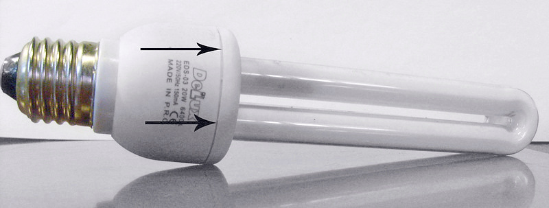
Energy-saving lamps, or compact fluorescent lamps (CFLs), can be roughly divided into two parts:
1) - itself fluorescent Lamp
2) - an electronic starting and regulating device (electronic ballast, electronic ballast) built into the lamp base.
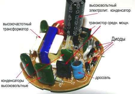
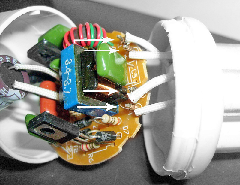
Let's take a closer look at what is in the electronic ballast:
Light color and color accuracy are challenges faced by many buyers. Just like luminosity, manufacturers must put the color of light in Kelvin on their products. This is the easiest way: the lower colour temperature, the warmer the light with a red tint, and the higher the colder the light with a blue tint.
Color rendering is one of the disadvantages of compact fluorescent lamps. Expressed in color rendering index. The higher the value, the better illuminated objects illuminated by this light with their natural color. For general lighting, the color rendering index is at least 80%; most of the tested compact fluorescent lamps meet this problem. For purposes where color accuracy is important, this is the most common cooking of general household chores, but you should target a source with a higher CRI, such as halogen bulbs.
Diodes - 6 pcs. High-voltage (220 Volts) are usually low-power (no more than 0.5 Amperes).
- Choke. (removes network interference).
- Medium power transistors (usually MJE13003).
- High voltage electrolyte. (usually 4.7 μF at 400 volts).
- Conventional capacitors of different capacities, but all at 250 volts.
- Two high frequency transformers.
- Several resistors.
From time to time there are rumors that compact fluorescent lamps and other energy saving light sources may have negative consequences for health. One of the most common problems is the mercury content of compact fluorescent lamps and the risks of rupture. As it is with its content, read the text on the impact of energy efficient light sources on the environment. All sources during operation comply with applicable standards, escape of volatiles organic compounds and others harmful substances, then when the light from them does not emit any harmful substances.
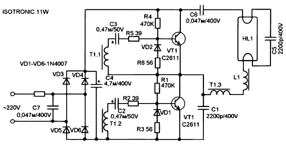
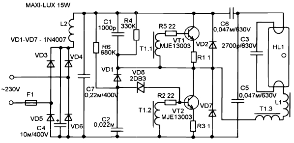
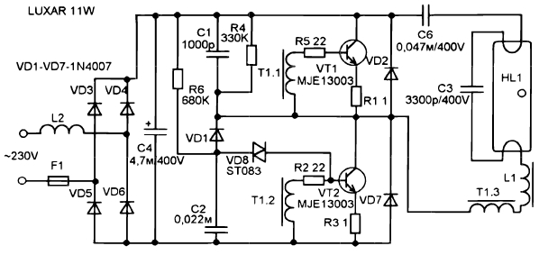
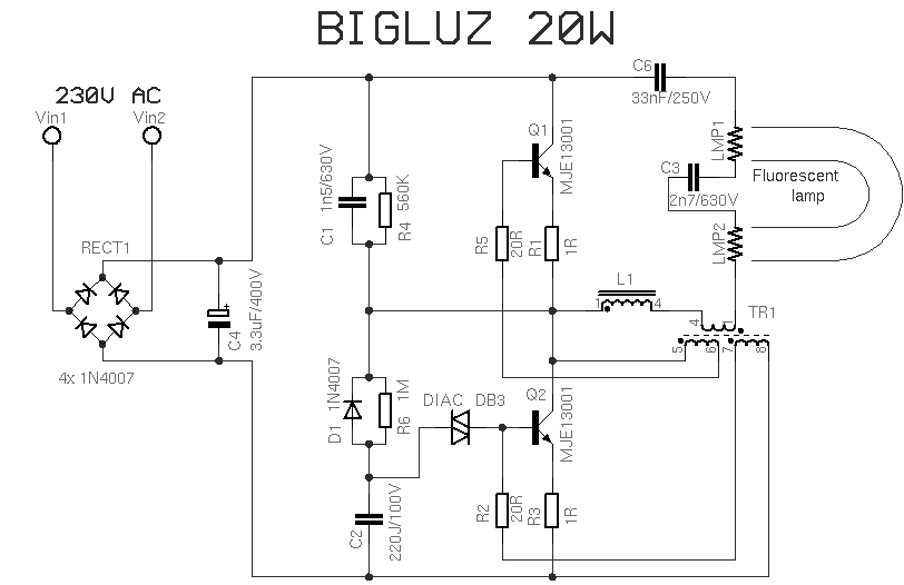
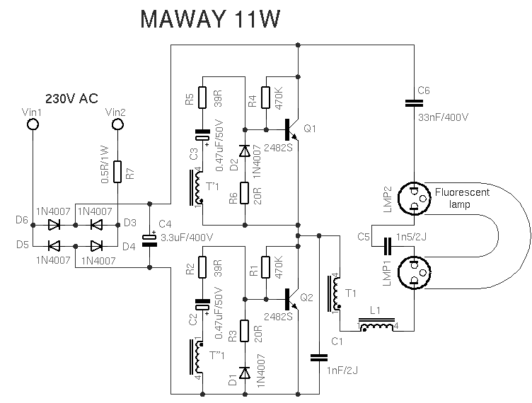
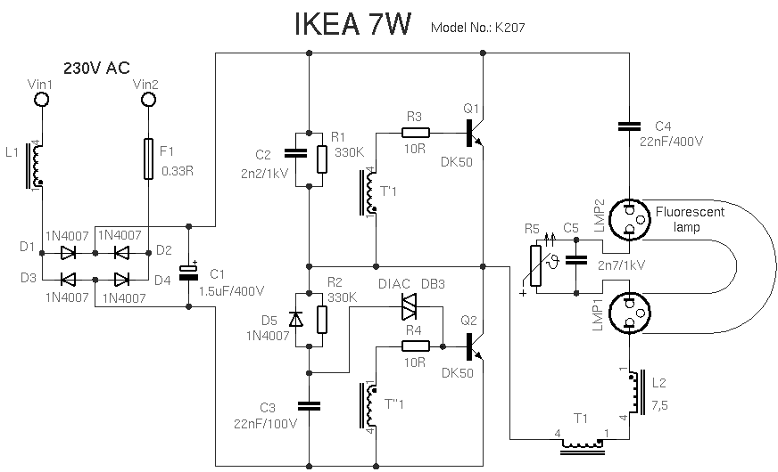
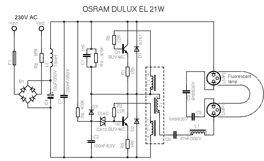
Let's analyze the work energy saving lamp using the most common scheme as an example
(11W lamp).
The circuit consists of power supply circuits, which include an anti-interference choke L2, a fuse F1, a diode bridge consisting of four 1N4007 diodes and a filter capacitor C4. The starting circuit consists of elements D1, C2, R6 and a dinistor. D2, D3, R1 and R3 are protective functions. Sometimes these diodes are not installed in order to save money.
Measurement of electromagnetic fields fell similarly. Nothing that would lead to problems. Compact fluorescent really minimal quantity ultraviolet radiation they radiate. This could potentially increase the risk of skin irritation in light-sensitive people, but only if they have spent long periods of time within a few centimeters of lit lamps. Although the risk is no greater than that of incandescent bulbs. If you are still concerned, we recommend purchasing ball shaped energy saving bulbs.
When the lamp is turned on, R6, C2 and the dynistor form a pulse fed to the base of the transistor Q2, leading to its opening. After starting, this part of the circuit is blocked by diode D1. Each time Q2 turns on, C2 is discharged. This prevents reopening of the dinistor. The transistors drive the transformer TR1, which consists of a ferrite ring with three windings and several turns. The filament receives voltage through the capacitor C3 from the boosting resonant circuit L1, TR1, C3 and C6. The tube lights up at the resonant frequency determined by the capacitor C3, because its capacitance is much less than that of C6. At this moment, the voltage across the capacitor C3 reaches about 600V. During start-up, the peak currents are 3-5 times the normal, so if the bulb is damaged, there is a risk of damage to the transistors.
They have two layers of glass separating the surroundings from the fluorescent lamps. It is preferable that the energy saving lamps still illuminate than on and off. Result? No higher consumption with frequent flicker. Consider, however, that some compact fluorescent lamps are not suitable for frequent switching on and off and take tens of seconds to accelerate to full luminosity.
Many energy costs, such as transportation, are also the same as saving resources. In the beginning, then pay nothing for too long. Together, you pay more. Save buy energy saving light bulbsand then enjoying lower electricity bills is obviously not so attractive for many people.
When the gas in the tube is ionized, C3 is practically shunted, so that the frequency is lowered and the generator is controlled only by the capacitor C6 and generates less voltage, but still enough to keep the lamp glowing.
When the lamp is lit, the first transistor turns on, which saturates the TR1 core. Feedback to the base causes the transistor to close. Then the second transistor is opened, driven by the oppositely connected winding TR1 and the process is repeated.
We looked at energy saving lamps in terms of their environmental impact, not only in terms of energy savings, but also in terms of their composition and the overall burden they bring to the environment. The results are amazing in many ways. Energy efficiency is the first factor for the overall environmental impact occurs. In simple terms, it is about how many lumens of light a fluorescent light bulb can produce, or one watt of power consumption. Compared to incandescent lamps, where the dependence of consumption on light is made much easier to save resources differ.
Faults in energy saving lamps
Most common reasons breakdown of energy-saving lamps - breakage of the filament or failure of the electronic ballast. As a rule, the reason for the failure of the latter is the breakdown of the resonant capacitor or transistors. Capacitor C3 often fails in lamps that use cheap, low voltage components. When the lamp stops igniting, there is a risk of failure of transistors Q1 and Q2 and, as a result, R1, R2, R3 and R5. When the lamp is started, the generator is overloaded and the transistors cannot withstand overheating. If the lamp bulb fails, the electronics usually also breaks down, mainly power transistors burn out. If the bulb is already old, one of the spirals may burn out and the lamp will stop working. Electronics in such cases, as a rule, remains intact.
Most often, lamps burn out at the moment they are turned on.
We find among them more and less effective products. The higher the efficiency, no doubt, however, some models can in the same product consumption twice as much light as others. Test tubes are made from one watt 35-65 lumens, the same as energy saving bulbs.
The longer the light source lasts, the more environmentally friendly, since the burden on the environment as a result of its production spreads over a longer period of time; Simply put - instead of several products, just make one. Life criteria are given for various resource saving technologies. Halogen lamps not during the life of the change or loss of light, so there is a main criterion for the total number of hours that the last light.
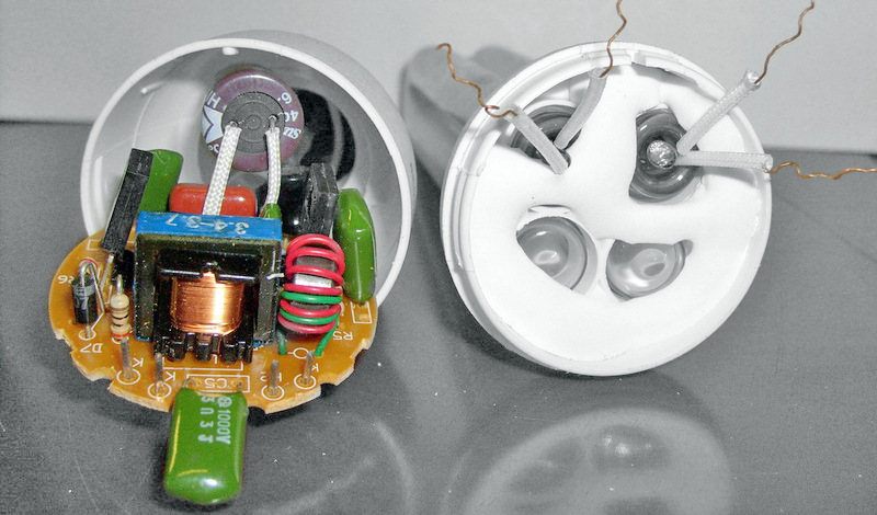
As a rule, the lamp is assembled with clips.
You need to disassemble it:
![]()
Disable the flask:
We check with an Ohmmeter the filament of the bulb.
Lamp repair.
If at least one of the spirals has burned out, we throw away the flask, if not, then it is working, and the circuit does not work.
In the next step, we began to dismantle the tested lights. First, we investigated whether leakage savings could be undesirable during lamp operation. chemical substances - especially mercury vapor and volatile organic compounds. Here we did not find any operational problems and all sources were tested completely safe.
Neither mercury content should be feared. The vast majority of fires contained less than 1 mg of mercury, which is five times less than the legal limit. For comparison, clinical thermometers, mercury contains about 500 mg of mercury. The immediate danger of broken energy-saving lamps is therefore minimal compared to the thermometer. The good news is that the amount of mercury is unrelated to light output and the best products they can shine just as well with minimal amounts.
In some cases, it is possible to restore the working capacity of a lamp with a burned-out spiral by closing it. Alternatively, close it with a high-power 8-10 Ohm resistor and remove the diode shunting this spiral, if any.
If the fuse blows out (sometimes it is in the form of a resistor), which usually happens when the capacitor C3 breaks down, the transistors Q1, Q2 are probably faulty, as a rule, transistors MJE13003 and resistors R1, R2, R3, R5 are used. Instead of a blown fuse, you can install a resistor of several ohms.
Its amount was approximately the same as for fluorescent lamps, that is, less than 1 mg. Below this tag we can find a proposal for both indoor and outdoor lighting. These luminaires are intended exclusively for our market and the Czech customer. The products are carefully designed in terms of marketability, which means that we try to design luminaires with great value and still high quality.
These lamps are made only inside the home, are characterized by a heavy-duty design and can be found in both modern and classic interiors. 
Each of these lights has its own distinctive style, and if the original interior is initially selected and positioned, it changes as well.
Before assembly, ventilation holes must be drilled in the lamp base to soften the operating temperature. A series of holes around the lamp tube attachment point serves to remove heat from the tube itself. A series of holes closer to the metal part of the base / plinth serves to conduct heat away from the ballast components. You can also make another row of holes - in the middle, with a larger diameter.

This catalog is intended for all types of clients, it contains all the main directions of both modern and classic lighting, that is, we are talking about a catalog where you can find a chandelier chandelier and technical spotlight equipped with the most modern source. Simple and elegant linear minimalism and design reliability, creativity and modernism, general harmony of forms. The lights are full of life, it is a festival of colors and shapes, it brings energy and fights against the conventions of optimism and have a good mood... Back to the original and the authenticity of the endless harmony and comfort of the traditional and the avant-garde. 
Elegance and intimacy, nostalgia, classic and baroque style. ... Good bathroom lighting is valuable because the area requires clear light to see what you are doing, so general lighting that is comfortable and enjoyable in the morning after waking up.
This upgrade of the energy saving lamp will help to significantly extend its life. Do not install the retrofitted lamp in places with high humidity (for example, a bathroom).
The most favorable conditions for the operation of energy-saving bulbs are in open form, or - a wide plafond or a plafond with ventilation, base up.
This is a ready-to-install kit designed for the bathroom. They provide clear, clear light that will immediately appear in the areas where it is needed most, creating a completely pleasant and relaxed atmosphere. They are also known to be easy to install and maintain.
These lights are important in understanding how they are indicated. The first number defines the degree of protection against the penetration of solid objects. The second parameter determines the degree of protection against water ingress. The higher the index value, the darker the light structure.
TYPICAL CIRCUITS FOR ENERGY-SAVING LAMPS
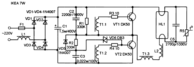
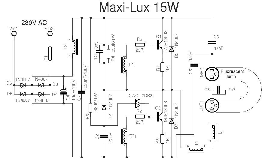
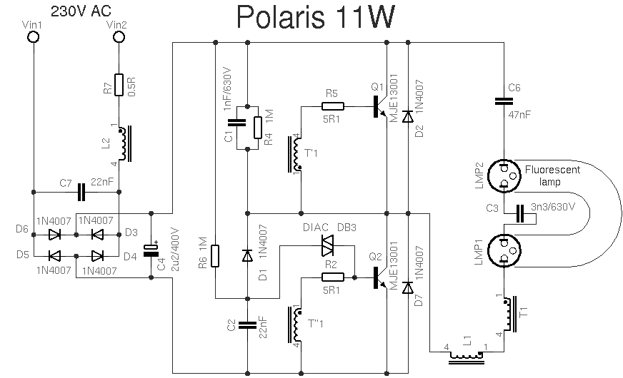
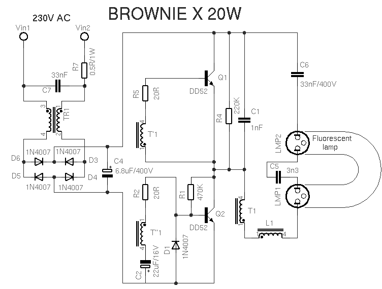
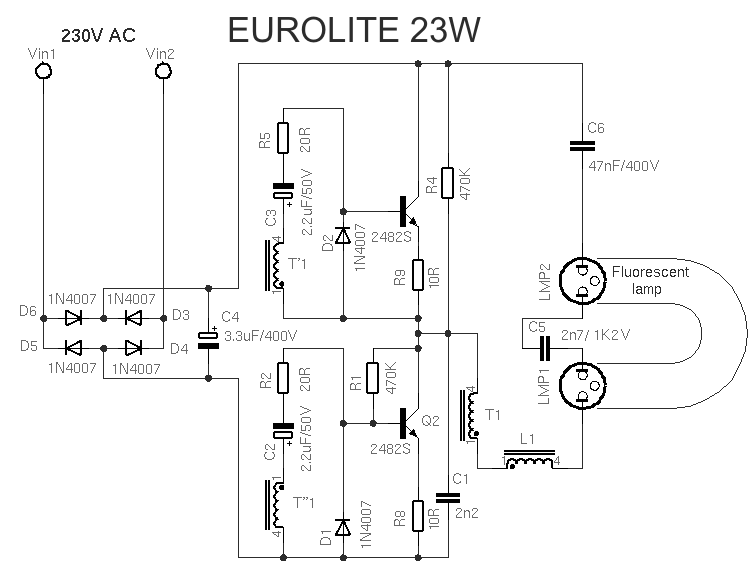
Below are popular schemes for economical fluorescent lamps, they are all made according to the same principle and, as a rule, are very similar.
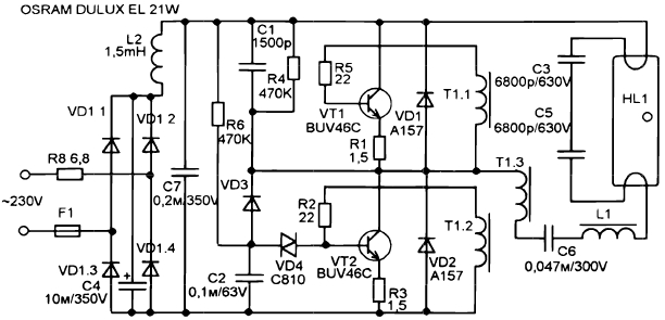
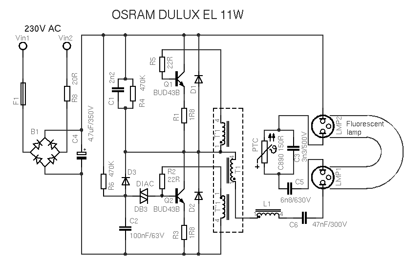
Osram energy saving lamp circuit
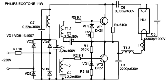
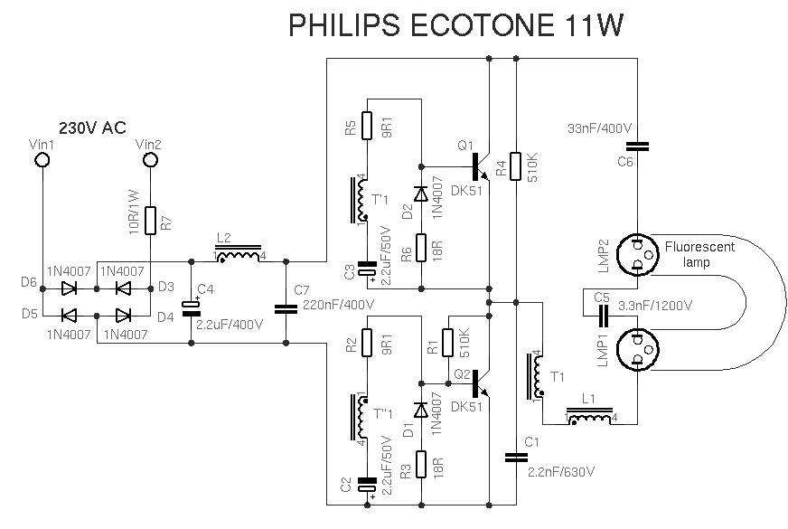
Philips energy saving lamp circuit

The following table provides an overview of the protection ranges allowed for individual bathroom zunas. 
When installing or renovating a more prominent and highly occupied space, such as a kitchen, lighting becomes a non-existent part of the project. Proper lighting improves functionality, appearance and the energy of the kitchen, as well as very important for your comfort, health and safety.
![]()
![]()
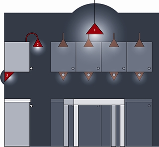
Since the kitchen is multifunctional, it is important to use appropriate lighting in the kitchen. There are three types of lighting: central and inadequate lighting, spotlight, built-in lighting. Centralized and indirect lighting provides complete illumination. It fills the room with gentle light, but if it's the only light source, we'll always work in our own dirt.
A spotlight provides illumination of desired objects or illuminates an enclosed space. Built-in illumination ensures illumination of the work surfaces and therefore safety of cooking. These lights can be fluorescent or halogen.
![]()
You can freely combine the individual elements according to your needs to create an elegant and compact look. Preparing a surface that is easy to clean. Otherwise, the kitchen is hygienic. Easy Installation It doesn't matter if you are renovating an old kitchen or getting a new one.
This concept is characterized by high quality ceiling and spot lighting. A majestic balance between quality, design and price. The highest quality materials are used. 
Various studies show that there is a direct link between appropriate lighting and productivity: if they have enough support, attention will remain. Therefore, it is clear that the right type of lighting increases the workload and significantly reduces the risk of anxiety, exhaustion and headaches.
Possible circuit for switching on PHILLIPS lamps 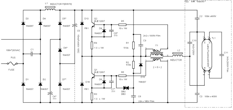
In this article, you will find a detailed description of the manufacturing process of switching power supplies of different power based on the electronic ballast of a compact fluorescent lamp.
You can make a 5… 20 Watt switching power supply in less than an hour. It will take several hours to make a 100-watt power supply. You can make more powerful electronic transformers, for example, on the IR2153, or you can BUY READY and remake it for your voltages.
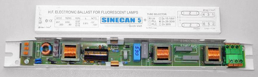
Currently, Compact Fluorescent Lamps (CFLs) are widely used. To reduce the size of the ballast choke, they use a high frequency voltage converter circuit, which can significantly reduce the size of the choke.
In the event of a failure of the electronic ballast, it can be easily repaired. But, when the bulb itself fails, the light bulb is usually thrown away.
However, the electronic ballast of such a light bulb is an almost ready-made switching power supply unit (PSU), and quite compact. The only difference between the electronic ballast circuit and a real switching power supply is the absence of an isolation transformer and rectifier, if necessary.
At the same time, modern radio amateurs are experiencing great difficulty in finding power transformers to power their homemade products. Even if a transformer is found, its rewinding requires the use of a large amount of copper wire, and the mass-dimensional parameters of products assembled on the basis of power transformers are not encouraging. But in the vast majority of cases power transformer can be replaced with a switching power supply. If, for these purposes, ballast from faulty energy-saving lamps is used, then the savings will be significant, especially when it comes to transformers of 100 watts and more.
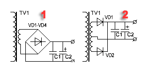
The difference between the ballast circuit of an energy-saving lamp from pulse unit nutrition
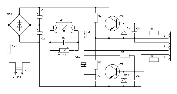
This is one of the most common electrical circuits for energy saving lamps. To convert the CFL circuit into a pulsed power supply, it is enough to install only one jumper between points A - A 'and add a pulse transformer with a rectifier. Items that can be deleted are marked in red.
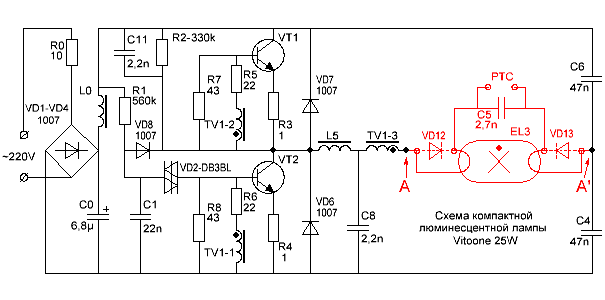
Energy saving lamp circuit
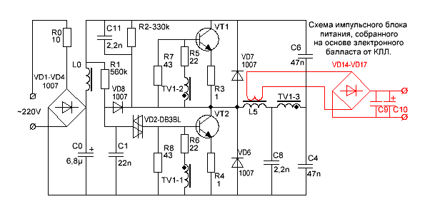
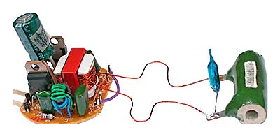
And this is an already finished circuit of a switching power supply, assembled on the basis of a fluorescent lamp ballast using an additional pulse transformer.
For simplicity, the fluorescent lamp and a few parts have been removed and replaced with a jumper.
As you can see, the CFL circuit does not require major changes. Additional elements introduced into the scheme are marked in red.

Completed switching power supply circuit
What power supply unit can be made from CFL?
The power of the switching power supply is limited by the overall power of the pulse transformer, the maximum allowable current of the key transistors and the size of the cooling radiator, if used.
A small power supply can be built by winding the secondary winding directly onto the frame of an existing choke.
PSU with a secondary winding directly onto the frame of an existing choke
If the choke window does not allow winding the secondary winding or if you need to build a power supply with a power that significantly exceeds the CFL power, then you will need an additional pulse transformer.
PSU with additional pulse transformer
If you need to get a power supply with a power of more than 100 watts, and ballast is used from a 20-30 watt lamp, then most likely you will have to make minor changes to the electronic ballast circuit.
In particular, it may be necessary to install more powerful VD1-VD4 diodes in the input bridge rectifier and rewind the input inductor L0 with a thicker wire. If the current gain of the transistors is insufficient, then the base current of the transistors will have to be increased by reducing the values \u200b\u200bof the resistors R5, R6. In addition, you will have to increase the power of the resistors in the base and emitter circuits.
If the generation frequency is not very high, then it may be necessary to increase the capacitance of the blocking capacitors C4, C6.
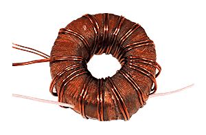
Pulse transformer for power supply

A feature of self-excited half-bridge switching power supplies is the ability to adapt to the parameters of the used transformer. And the fact that the feedback loop will not pass through our homemade transformer makes the task of calculating the transformer and setting up the unit even easier. Power supplies assembled according to these schemes forgive errors in calculations up to 150% and higher. Tested in practice.
Don't be alarmed! You can wind a pulse transformer during watching one movie or even faster if you are going to do this monotonous work with concentration.
Input filter capacity and voltage ripple
In the input filters of electronic ballasts, due to space saving, small capacitors are used, on which the magnitude of the voltage ripple with a frequency of 100 Hz depends.
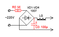
To reduce the level of voltage ripple at the output of the power supply, you need to increase the capacitance of the input filter. It is desirable that for every watt of power supply there is one microfarad or so. An increase in the capacity C0 will entail an increase in the peak current flowing through the rectifier diodes at the moment the power supply is turned on. To limit this current, a resistor R0 is needed. But, the power of the original CFL resistor is small for such currents and should be replaced with a more powerful one.
If you need to build a compact power supply, you can use electrolytic capacitors used in flash lamps of film "mallnits". For example, Kodak disposable cameras have unmarked miniature capacitors, but their capacitance is as much as 100µF at 350 volts.
20 Watt power supply
20 watt power supply
A power supply unit with a capacity close to that of the original CFL can be assembled without even winding a separate transformer. If the original choke has enough free space in the magnetic circuit window, then you can wind a couple of dozen turns of wire and get, for example, a power supply for a charger or a small power amplifier.
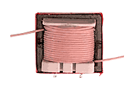
The picture shows that one layer was wound over the existing winding insulated wire... I used MGTF wire (fluoroplastic insulated stranded wire). However, in this way, you can get a power of only a few watts, since most of the window will be occupied by the insulation of the wire, and the cross section of the copper itself will be small.
If more power is required, ordinary copper varnished winding wire can be used.
Attention! The original choke winding is under mains voltage! With the revision described above, be sure to worry about reliable interwinding insulation, especially if the secondary winding is wound with an ordinary varnished winding wire. Even primary winding covered with a synthetic protective film, additional paper spacer required!

As you can see, the winding of the choke is covered with a synthetic film, although often the winding of these chokes is not protected by anything at all.
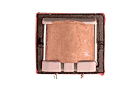
We wind two layers of electrical cardboard with a thickness of 0.05 mm or one layer with a thickness of 0.1 mm over the film. If there is no electrical cardboard, we use any paper of suitable thickness.
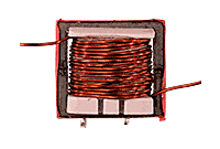
We wind the secondary winding of the future transformer on top of the insulating gasket. The wire cross-section should be selected as large as possible. The number of turns is selected experimentally, since there will be few of them.
Thus, I managed to get power at a load of 20 watts at a transformer temperature of 60 ° C, and transistors - 42 ° C. To get even more power, at a reasonable temperature of the transformer, was not allowed by the too small area of \u200b\u200bthe magnetic circuit window and the resulting wire section.
The picture shows the current PSU model
The power supplied to the load is 20 watts.
Self-oscillation frequency without load - 26 kHz.
Self-oscillation frequency at maximum load - 32 kHz
Transformer temperature - 60? С
Transistor temperature - 42? С
To increase the power of the power supply, a TV2 pulse transformer had to be wound. In addition, I increased the capacitance of the mains voltage filter C0 to 100µF.
100 watt power supply
Since the efficiency of the power supply is not at all 100%, we had to screw some radiators to the transistors.
After all, if the efficiency of the unit is even 90%, you will still have to dissipate 10 watts of power.
![]()
I was not lucky, in my electronic ballast transistors 13003 pos. 1 of such a design were installed, which, apparently, is designed to be fastened to the radiator using shaped springs. These transistors do not need spacers, since they are not equipped with a metal pad, but they give off heat much worse. I replaced them with transistors 13007 pos. 2 with holes so that they could be screwed to the radiators with ordinary screws. In addition, 13007 have several times higher maximum permissible currents. You can buy MJE13007 separately.
If you wish, you can safely screw both transistors onto one radiator. I checked it works.
Only, the housings of both transistors must be insulated from the heatsink housing, even if the heatsink is inside the electronics housing.
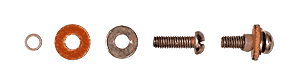
It is convenient to fasten it with M2.5 screws, on which you must first put on insulating washers and pieces of insulating tube (cambric). It is allowed to use KPT-8 heat-conducting paste, as it does not conduct current.
Attention! The transistors are under mains voltage, therefore, the insulating gaskets must ensure electrical safety conditions!
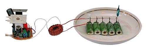
Operating 100-watt switching power supply
The dummy load resistors are immersed in water as their power is insufficient.
The power allocated to the load is 100 watts.
Self-oscillation frequency at maximum load - 90 kHz.
Self-oscillation frequency without load - 28.5 kHz.
The temperature of the transistors is 75 ° C.
The radiator area of \u200b\u200beach transistor is 27cm?
Choke temperature TV1 - 45 ° C.
TV2 - 2000NM (O28 x O16 x 9mm)
Rectifier
All secondary rectifiers of a half-bridge switching power supply must be full-wave. If this condition is not met, then the magnetic conductor may enter saturation.
There are two common full-wave rectifier circuits.
1. Bridge scheme.
2. Circuit with zero point.
The bridge circuit saves a meter of wire, but dissipates twice as much energy on the diodes.
A zero point circuit is more economical, but requires two perfectly symmetrical secondary windings. Asymmetry in the number of turns or location can lead to saturation of the magnetic circuit.
However, it is precisely zero-point circuits that are used when it is required to obtain high currents at low output voltage. Then, for additional minimization of losses, instead of conventional silicon diodes, Schottky diodes are used, on which the voltage drop is two to three times less.
Example.
Rectifiers of computer power supplies are made according to the zero point scheme. With a power output of 100 watts and a voltage of 5 volts, 8 watts can dissipate even on Schottky diodes.
100/5 * 0.4 \u003d 8 (Watt)
If we use a bridge rectifier, and even ordinary diodes, then the power dissipated on the diodes can reach 32 watts or even more.
100/5 * 0.8 * 2 \u003d 32 (Watt).
Pay attention to this when you design the power supply, so that later you do not look for where half the power disappeared.
In low voltage rectifiers, it is better to use a zero point circuit. Moreover, with manual winding, you can simply wind the winding in two wires. In addition, high-power pulse diodes are not cheap.
How to properly connect the switching power supply to the network?
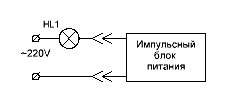
To set up switching power supplies, they usually use the following connection scheme. Here, the incandescent lamp is used as a ballast with a non-linear characteristic and protects the UPS from failure during abnormal situations. The power of the lamp is usually chosen close to the power of the pulsed power supply under test.
When a pulsed power supply unit is operating at idle or at a low load, the resistance of the lamp cocoa filament is small and it does not affect the operation of the unit. When, for some reason, the current of the key transistors increases, the spiral of the lamp becomes heated and its resistance increases, which leads to the limitation of the current to a safe value.
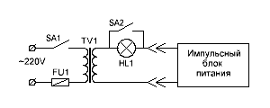
This drawing shows a diagram of a stand for testing and adjusting pulsed power supplies that meets electrical safety standards. The difference between this circuit and the previous one is that it is equipped with an isolation transformer, which provides galvanic isolation of the UPS under study from the lighting network. The SA2 switch allows you to block the lamp when the power supply delivers more power.
An important operation when testing a PSU is a dummy load test. It is convenient to use powerful resistors such as PEV, PPB, PSB, etc. as a load. These "glass ceramic" resistors are easy to find on the radio market for their green color scheme. Red numbers are power dissipation.
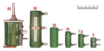
It is known from experience that for some reason the power of the equivalent load is always not enough. The resistors listed above can dissipate power two to three times the nominal for a limited time. When the power supply unit is turned on for a long time to check the thermal regime, and the power of the equivalent load is insufficient, then the resistors can simply be dipped into the water.
Be careful not to burn!
Terminating resistors of this type can heat up to a temperature of several hundred degrees without any external manifestations!
That is, you will not notice any smoke or color change and you can try to touch the resistor with your fingers.
How to set up a switching power supply?
Actually, the power supply, assembled on the basis of a serviceable electronic ballast, does not require special adjustment.
It must be connected to a dummy load and make sure that the PSU is capable of delivering the rated power.
During a run under maximum load, you need to follow the dynamics of the temperature rise of transistors and transformer. If the transformer heats up too much, then you need to either increase the wire cross-section, or increase the overall power of the magnetic circuit, or both.
If the transistors are very hot, then you need to install them on the radiators.
If a home-wound choke from CFL is used as a pulse transformer, and its temperature exceeds 60 ... 65? С, then it is necessary to reduce the load power.
IMPULSE POWER SUPPLY UNIT FROM ENERGY-SAVING LAMPS low-power switching power supply from improvised materials with your own hands
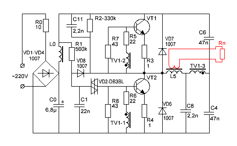
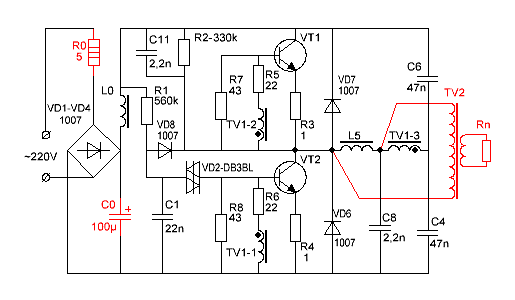
What is the purpose of the elements of the switching power supply circuit?
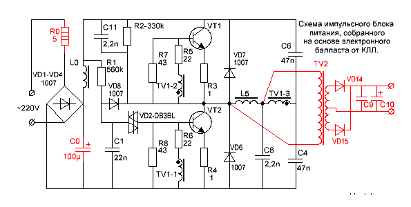
Switching power supply circuit
R0 - limits the peak current flowing through the rectifier diodes at the moment of switching on. CFLs also often function as a fuse.
VD1… VD4 is a bridge rectifier.
L0, C0 - power filter.
R1, C1, VD2, VD8 - converter start circuit.
The launch node works as follows. The capacitor C1 is charged from the source through the resistor R1. When the voltage across the capacitor C1 reaches the breakdown voltage of the VD2 dinistor, the dinistor unlocks itself and unlocks the VT2 transistor, causing self-oscillations. After the onset of generation, rectangular pulses are applied to the cathode of the VD8 diode and the negative potential reliably blocks the VD2 dinistor.
R2, C11, C8 - make it easier to start the converter.
R7, R8 - improve the blocking of transistors.
R5, R6 - limit the base current of the transistors.
R3, R4 - prevent saturation of transistors and act as fuses during breakdown of transistors.
VD7, VD6 - protect transistors from reverse voltage.
TV1 is a feedback transformer.
L5 - ballast choke.
C4, C6 - blocking capacitors, on which the supply voltage is divided in half.
TV2 is a pulse transformer.
VD14, VD15 - pulse diodes.
C9, C10 - filter capacitors.
Based on materials from the site http://www.ruqrz.com/
For greater clarity, several schematic diagrams lamps of popular manufacturers: