Measuring the power of direct electric current. §102. Measurement of power and electrical energy
Work plan
Various methods of measuring power and methods of connecting devices in circuits direct current.
Analysis of measurement results.
Basic theoretical provisions
Power is a physical quantity equal to the work performed per unit of time, which is equivalent to the rate of change in the energy of the system. In particular, electrical power is a quantity that characterizes the rate of transfer or conversion of electrical energy into other forms of energy, for example, mechanical, thermal, light, etc.
DC powerdefined by the expression P = UI, where U - voltage, applied to the load, V, I – current flowing through the load, A. Unit of measurement electrical power is the watt (W). From the above equation it follows that the power P can be determined indirectly by measuring the voltage with a voltmeter U on load and ammeter - current I, flowing through the load. Multiplying the measurement results U and I, we get the power value.
In fig. 1 shows two schemes for switching on a voltmeter and an ammeter. The choice of a particular scheme is due to the permissible methodological measurement error. The error depends on the commensurability of the internal resistances of the devices with the load resistance R n .
Figure: 1. Power metering circuits
in the DC circuit.
Scheme fig. 1 and applies when load resistance R n much less resistance of the voltmeter R in ; and the diagram in Fig. 1 b - when the load resistance R n a lot of more resistance ammeter R a ... If these conditions are neglected and it is assumed that R n = R in for the circuit in Fig. 1 and and R n = R a for the circuit in Fig. 1 b, then the relative error in power measurement will be 100%.
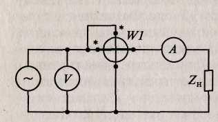
It is more convenient to measure power with one device - a wattmeter. To determine the power, the wattmeter needs information about current and voltage, and it must be able to multiply them. Such a device is an electrodynamic wattmeter, consisting of a moving coil located inside a stationary coil.
The load voltage is connected to the moving coil, and the load current is passed through the fixed coil. The interaction of the magnetic fields of the coils causes the moving coil to rotate through an angle proportional to the power. The direction of rotation depends on the direction of the currents in the coils, therefore it is necessary to include it in the circuit so that the beginning of the windings of the coils are connected towards the power source (generator). On the terminals of the wattmeter, the beginnings of the windings are marked with an asterisk (* U and * I). They are called generator clamps. If the current generator clamp is connected by mistake in the direction of the load, then the arrow of the device will deviate to the left from the zero mark and the reading will be impossible. The generator clamp of the voltage winding, in order to reduce the measurement error, can be switched on according to the diagram in Fig. 2 and or fig. 2 b.
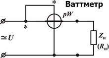
Figure: 2. Scheme for connecting a wattmeter to a DC circuit.
Scheme fig. 2 a is used when the load resistance R n much more resistance of the current circuit of the wattmeter R a ; and the diagram in Fig. 2 b - when the load resistance R n much less resistance of the wattmeter voltage circuit R in ... The resistances of the voltage and current circuits are indicated on the dial of the device. The wattmeter is designed in such a way that the circuit in Fig. 2 and.
Power measurement. In DC circuits, power is measured with an electro- or ferrodynamic wattmeter. Power can also be calculated by multiplying the current and voltage values \u200b\u200bmeasured with an ammeter and a voltmeter.
In chains single-phase current power measurement can be carried out with an electrodynamic, ferrodynamic or induction wattmeter. Wattmeter 4 (Fig. 336) has two coils: current 2, which is connected to the circuit in series, and voltage 3, which is connected to the circuit in parallel.
A wattmeter is a device that requires correct polarity when switched on, therefore its generator clamps (the clamps to which the conductors coming from the source 1 side are connected) are denoted with asterisks.
Figure: 336. Circuit for measuring power
To expand the measurement limits of wattmeters, their current coils are connected to the circuit using shunts or measuring current transformers, and voltage coils are connected through additional resistors or measuring voltage transformers.
Measurement of electrical energy. Measurement method... To account for electrical energy received by consumers or given by current sources, electricity meters are used. The electricity meter is similar in principle to a wattmeter. However, unlike wattmeters, instead of a spiral spring, which creates a counter-torque, the meters provide a device similar to an electromagnetic damper, which creates a braking force proportional to the speed of rotation of the moving system. Therefore, when the device is connected to an electrical circuit, the resulting torque will not cause a deflection of the moving system by a certain angle, but its rotation with a certain frequency.
The number of revolutions of the moving part of the device will be proportional to the product of power electric current for the time during which it acts, that is, the amount of electrical energy passing through the device. The number of revolutions of the counter is fixed by a counter mechanism. The gear ratio of this mechanism is chosen so that, according to the counter readings, not the revolutions, but directly the electrical energy in kilowatt-hours can be counted.
The most widespread are ferrodynamic and induction meters; the former are used in DC circuits, the latter in circuits alternating current... Electric energy meters are included in AC and DC electrical circuits in the same way as wattmeters.
Ferrodynamic counter (Fig. 337) set on e. p. from. direct current. It has two coils: a fixed 4 and a movable 6. The fixed current coil 4 is divided into two parts, which cover the ferromagnetic core 5 (usually of permalloy). The latter makes it possible to create a strong magnetic field and significant torque in the device, which ensures the normal operation of the meter under conditions of shaking and vibrations. The use of permalloy helps to reduce the error of the counting mechanism 2 from the hysteresis of the magnetic system (it has a very narrow hysteresis loop).
To reduce the influence of external magnetic fields on the meter readings, the magnetic fluxes of individual parts of the current coil have a mutually opposite direction (astatic system). In this case, the external field, weakening the flux of one part, accordingly increases the flux of the other part and has a generally small effect on the resulting torque generated by the device. The moving coil 6 of the counter (voltage coil) is located on an armature made in the form of a disk made of insulating material or in the form of an aluminum bowl. The coil consists of separate sections connected to the collector plates 7 (these connections are not shown in Fig. 337), along which brushes made of thin silver plates slide.
The ferrodynamic meter works in principle as a direct current motor, the armature winding of which is connected in parallel, and the excitation winding is in series with the electricity consumer. The armature rotates in an air gap between the poles of the core. The braking torque is created as a result of the interaction of the flow of the permanent magnet 1 with eddy currents arising in the aluminum disk 3 during its rotation.
To compensate for the influence of the friction moment and thereby reduce the errors of the device in ferrodynamic meters, a compensation coil is installed or a petal made of permalloy is placed in the magnetic field of a stationary (current) coil, which has a high magnetic permeability at low field strength. At light loads, this lobe amplifies the magnetic flux of the current coil, which leads to an increase in torque and friction compensation. With increasing load induction magnetic field the coil increases, the petal is saturated and its compensating effect ceases to increase.
When the meter is running on e. p. from. strong shocks and impacts are possible, in which the brushes can bounce off the collector plates. This will create sparks under the brushes. To prevent it, a capacitor C and a resistor R1 are included between the brushes. Compensation of the temperature error is carried out using a thermistor RT (a semiconductor device whose resistance depends on temperature). It is switched on together with an additional resistor R2 in parallel with the moving coil. To reduce the influence of shaking and vibrations on the operation of meters, they are installed on e. p. from. on rubber-metal shock absorbers.
Induction counter has two electromagnets (Fig. 338, a), between which there is an aluminum disk 7. The torque in the device is created as a result of the interaction of alternating magnetic fluxes F1 and F2, created by the coils of electromagnets, with eddy currents I в1 and I в2, induced by them in aluminum disk (as in a conventional induction measuring mechanism, see § 99).
In an induction meter, the torque M must be proportional to the power P \u003d UIcos ?. For this, the coil 6 of one of the electromagnets (current) is connected in series with the load 5, and the coil 2 of the other (voltage coil) is connected in parallel with the load. In this case, the magnetic flux F1 will be proportional to the current I in the load circuit, and the flux F2 will be proportional to the voltage U applied to the load. To ensure the required phase angle? between the flows F1 and F2 (so that sin? \u003d cos?), a magnetic shunt 3 is provided in the electromagnet of the voltage coil, through which part of the flow F2 is closed
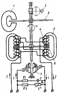
Figure: 337. Ferrodynamic meter of electrical energy
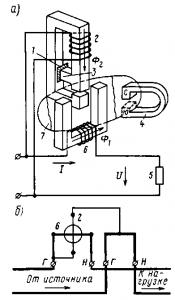
Figure: 338. Induction electricity meter
in addition to the disk 7. The phase angle between the flows F1 and F2 is precisely controlled by changing the position of the metal shield 1 located in the path of the flow branching through the magnetic shunt 3.
The braking torque is generated in the same way as in a ferrodynamic counter. The frictional moment is compensated by creating a slight asymmetry in the magnetic circuit of one of the electromagnets using a steel screw.
To prevent the armature from rotating in the absence of a load under the action of the force created by the friction compensating device, a steel brake hook is attached to the meter axis. This hook is attracted to the brake magnet 4, thereby preventing the movable system from rotating without load.
When the counter is operating under load, the brake hook practically does not affect its readings.
In order for the counter disk to rotate in the required direction, it is necessary to observe a certain order of connecting wires to its terminals. The load clamps of the device, to which the wires coming from the consumer are connected, are denoted by the letters I (Fig. 338, b), the generator clamps, to which the wires from the current source or from the alternating current network are connected, by the letters D.
Topic: how to measure electrical power, methods, calculation methods.
What is power? Do you remember from the lessons of school physics? This physical quantity expresses the work done for a certain period of time. In general, power can be expressed as the rate of change in the energy of a particular system. With regard to electrical power, this expression will have a different form: a physical quantity that determines the rate of conversion or transmission of electricity. The formula for electrical power is even simpler than the spoken words - P \u003d U × I. That is, it is equal to the voltage multiplied by the amperage. Consequently, measurements of electrical power will be made according to this principle.
To carry out measurements of electrical power in practice, two are used. The first will be the use of a special measuring device called a wattmeter (for measuring DC power) and a varmeter (for measuring AC power). The second method is more common among electricians and is indirect. This is a common measurement of the base values \u200b\u200bof current and voltage and then multiplying them. For example, on a permanent electric motor, an inscription was erased on which the nominal electrical power of this electric motor... What to do? We take it and connect this engine to the power supply. Next, we measure the voltage at the input terminals and the current that is flowing at this moment. We multiply the first by the second, and as a result we get the average electric power of this electric motor.
The measurement of electrical power using electrical devices can be found more in special measuring laboratories, manufacturing workshops, development bureaus, etc. In practice, there is rarely a need to measure power using special devices. With regard to the classification of wattmeters. They can be divided into three main types (by purpose and frequency range): direct current (low frequency), radio frequency and optical. Depending on the direct version of the functional transformation of information (measuring) and its subsequent output, wattmeters are analog and digital. For electrical needs, the most suitable is the first type - low-frequency (direct current). They are the ones who measure electrical power in power systems.
DC wattmeters (and low-frequency current varmeters) are mainly used in electrical networks power supply of industrial frequency (50Hz) for measuring the consumed electric power. They are single-phase and three-phase. Varmeters constitute a separate group - reactive electrical power meters. Electronic digital devices usually combine measurements, both active and reactive power... Analog wattmeters (constant and low-frequency type) of a ferrodynamic or electrodynamic system have two copper coils in their device, one is connected in series with the electrical load, and the other is parallel to it. The interaction of the electromagnetic fields of these coils generates a torque that moves the needle of the measuring device.
![]() To measure electrical power with instruments, they are connected as follows. As we know, the voltage in electrical circuits is measured in parallel to the circuit, and in order to measure the current strength, it becomes necessary to break the direct section of the circuit in which the measurement takes place. If, to obtain electrical power, it is necessary to multiply the voltage with the current strength, then the measurements with the instruments are made according to the same principle as the separate measurement of current and voltage. Therefore, the wattmeter is connected at the same time, as in a gap electrical circuit, and in parallel.
To measure electrical power with instruments, they are connected as follows. As we know, the voltage in electrical circuits is measured in parallel to the circuit, and in order to measure the current strength, it becomes necessary to break the direct section of the circuit in which the measurement takes place. If, to obtain electrical power, it is necessary to multiply the voltage with the current strength, then the measurements with the instruments are made according to the same principle as the separate measurement of current and voltage. Therefore, the wattmeter is connected at the same time, as in a gap electrical circuit, and in parallel.
Power measurement.In a DC circuit, power can be measured with an ammeter and voltmeter, since P \u003dUI. However, it can be more accurately measured directly by the electrodynamic wattmeter(fig.10.3). It consists of a low-resistance coil, connected, like an ammeter, in series and called current winding,and a moving coil with high resistance, connected in parallel and called voltage winding.
The torque of the wattmeter is proportional to the product of the currents in the coils:
where I is the current in the stationary coil, practically equal to the load current; 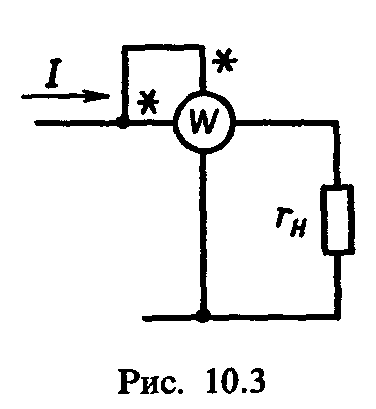 I U
=
U/
r U
- the current in the moving coil, i.e. in the voltage winding; r U
-
the resistance of the moving coil circuit. Hence,
I U
=
U/
r U
- the current in the moving coil, i.e. in the voltage winding; r U
-
the resistance of the moving coil circuit. Hence,
 (10.5)
where FROM -proportionality coefficient.
Thus, the torque of the wattmeter is proportional to the power and its scale can be calibrated directly in watts or kilowatts.
To measure active power in alternating current circuits, wattmeters of an electrodynamic system are used.
Measurement of active power in a single-phase circuit. An electrodynamic wattmeter for measuring active power in a single-phase AC circuit is turned on in the same way as when measuring in a DC circuit, that is, according to the scheme in Fig. 10.3. Since the current I U in moving coil proportional to voltage U and practically coincides with it in phase, and the current I in the stationary coil (current winding) is equal to the load current, then the torque of the wattmeter
where C is the coefficient of proportionality.
So, the torque of the wattmeter is proportional to the measured active power R,and opposing moment M etc , proportional to the angle of rotation α of the moving coil (or the arrow of the device). Therefore, the deviation of the arrow of the device is proportional to the measured power Rand, therefore, the wattmeter scale is graduated in watts or kilowatts.
Clamps of the current winding and voltage winding of the wattmeter, marked with asterisks and called generator sets,should be connected to the electrical circuit from the side of the power source.
Measurement of active power in a three-phase circuit. Depending on the nature of the load and the three-phase circuit diagram, several methods of power measurement are used.
With a symmetrical load, the active power in a three-phase circuit can be measured by measuring the power in one phase withusing a wattmeter connected according to the diagram in Fig. 10.4, a, b. After measurement, the reading
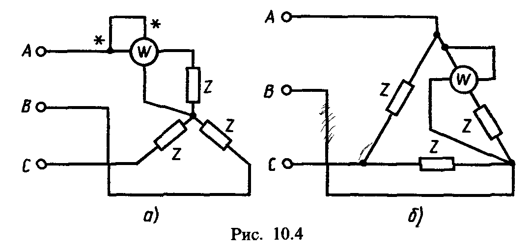
wattmeter P w multiply by 3: * "
(10.7)
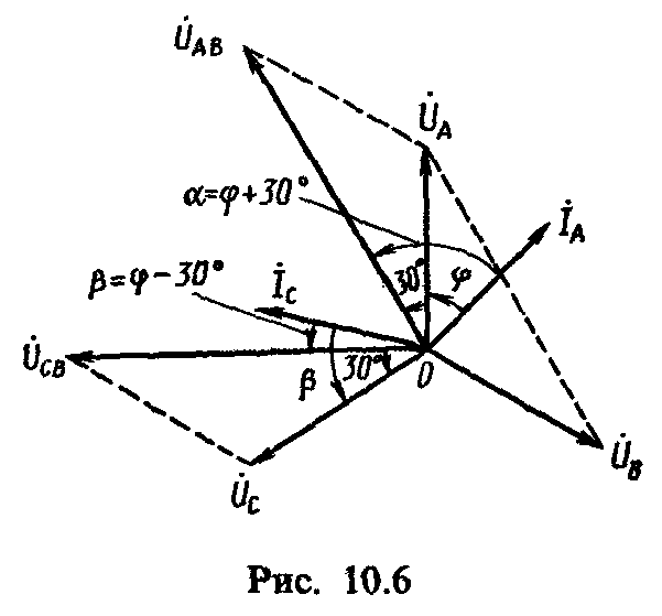
In a three-wire three-phase circuit, both with balanced and unbalanced loads and any method of connecting consumers, the active power can be measured using two wattmeters(fig.10.5). Let us show that the algebraic sum of the readings of the wattmeters in this case is equal to the active power Rin a three-wire three-phase circuit.
Instantaneous power value measured by the first wattmeter, p 1 \u003d u AB i A. Instantaneous power measured by the second wattmeter, p 2 \u003d u CB i C. The sum of the instantaneous power values \u200b\u200bmeasured by two wattmeters, p \u003dp 1 + p 2 = u AB i A + u CB i C . .
If line voltages and AB and u CB , to which the voltage windings of the wattmeters are connected, express through the phase voltages u AB = u A - u B ; u cb = and from - and in ,; then p \u003d and AND i A - u B i A + u c i c - u B i c or p \u003du A i A + u c i c - and in (i A + i c). Since in a three-wire three-phase circuit i A + i B + i C = 0, then i A + i C = - i B , , and the final expression of the power measured by two wattmeters,
It follows from this expression that the total instantaneous power measured by two wattmeters is equal to the active power in a three-phase circuit when consumers are connected by a star. Similar reasoning can be repeated for connecting consumers with a triangle, while obtaining the same final result.
The active power of a three-phase system, expressed through the effective values \u200b\u200bof voltages and currents and measured by the method of two wattmeters, is
where R w 1 and Р w 2 - readings of wattmeters.
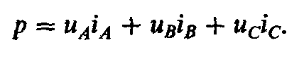
When measuring active power by the method of two wattmeters for the case of a symmetrical load I AND = I IN = I FROM = I l ; U AC \u003d U CB = U l .
Figure 10.6 shows a vector diagram of currents and voltages, which explains the measurement of active power using
two wattmeters for a symmetrical load connected in a star. Since on the vector diagram the angle α between the vectors U AB and I AND is φ + 30 °, and the angle β between the vectors U CB and I C is φ - 30 °, then the power of a three-phase system with a symmetrical load
If the phase angle φ< 60°, то, согласно (10.9), мощность, учитываемая ваттметрами, всегда положительна: R w1 = U L I L cos (φ + 30 °) and P w 2 = U L I L cos (φ - 30 °). At φ \u003d 60 °, the power shown by the first wattmeter is zero: cos (60 ° + 30 °) \u003d 0. In this case, all power in the three-phase circuit will be taken into account by the second wattmeter. At φ\u003e 60 °, the power taken into account by the first wattmeter becomes negative and the total power of the two wattmeters is calculated taking into account the sign of the powers of the latter, as their algebraic sum.
In practice, to read the negative power according to the readings of the wattmeter, it is necessary to change the direction of the current in the voltage winding, for which the switch for the direction of the current in the voltage winding, located on the wattmeter body, must be switched from "+" to "-".
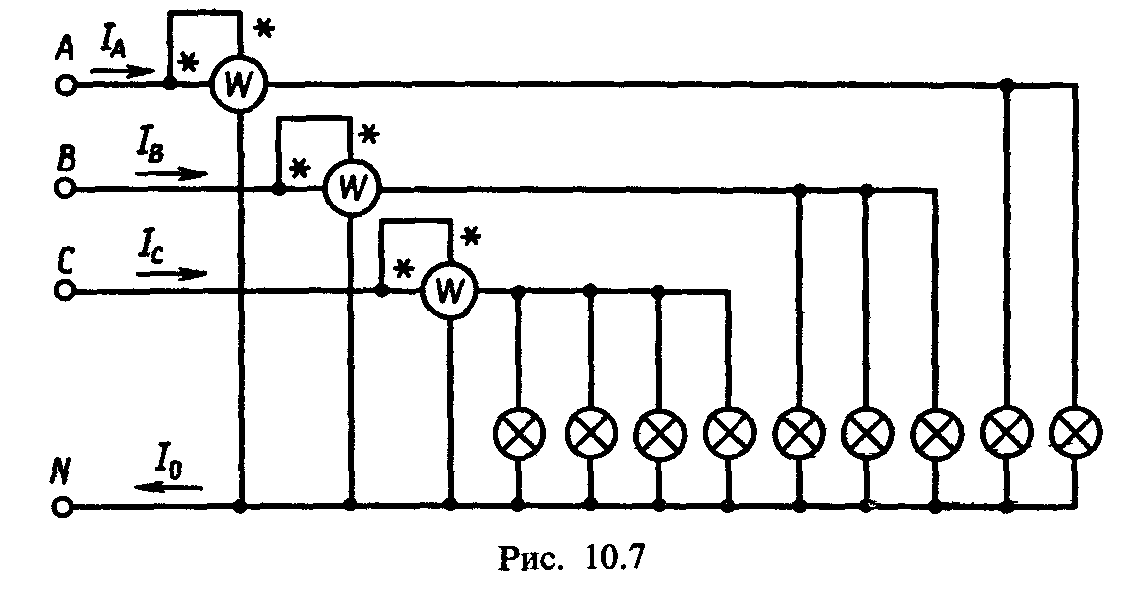
You can measure the active power in a four-wire three-phase circuit with an unbalanced load with three wattmeters (Figure 10.7). Since in this case each of the wattmeters measures the active power of one phase, then the power in a four-wire three-phase circuit
where R AND , R B , P C - active phase powers A, B, C.
Measurement of reactive power in a three-phase circuit... The reactive power in a three-phase three-wire circuit with a symmetrical load can be determined by the difference in the readings of the wattmeters (see Fig.10.5):
where is the reactive power
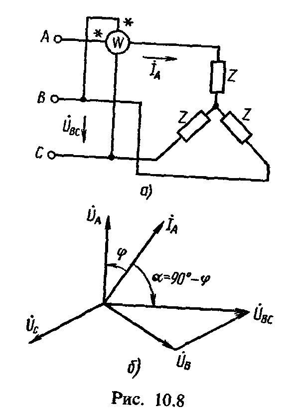
The reactive power in a three-wire three-phase circuit with a symmetrical load can be measured with one wattmeter (Fig. 10.8, and), and the current winding of the wattmeter is included in the linear wire AND,and the voltage winding - to line voltage U BC (ie, on "someone else's" voltage). From the vector diagram (Fig.10.8.6) it can be seen that the phase shift between the current I A and tension U BC is α \u003d 90 ° - φ. Then the readings of the wattmeter 4
To calculate the reactive power of a three-phase three-wire circuit with a symmetrical load, it is necessary to multiply the wattmeter readings by  :
:
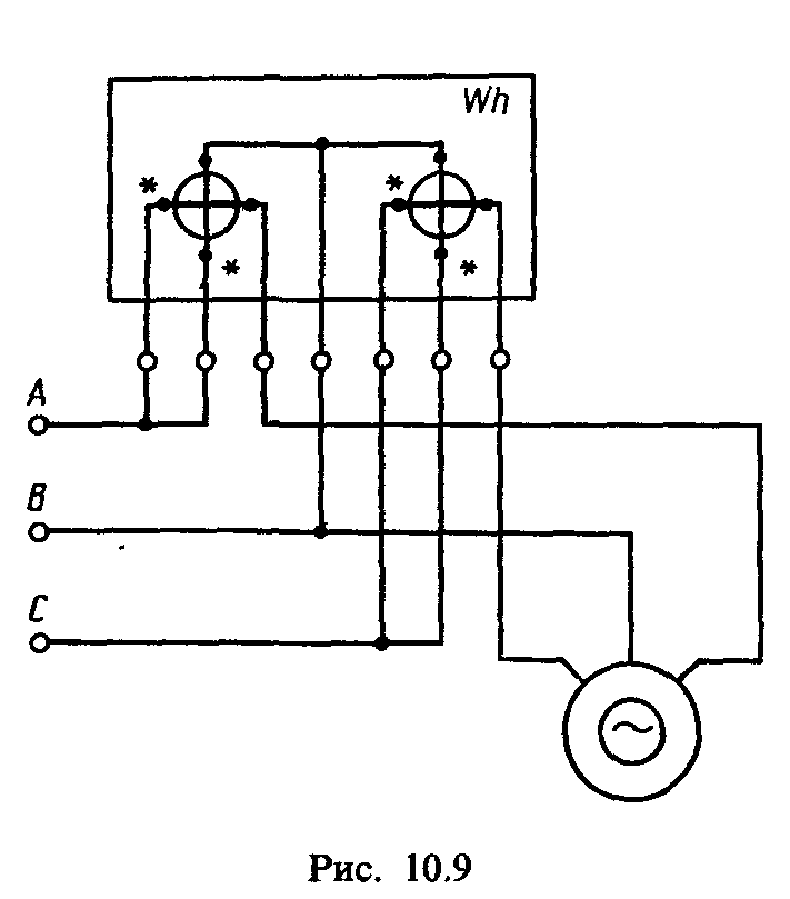
Energy measurement in AC circuits... In AC circuits, single-phase and three-phase are used to measure active energy countersinduction system. To measure active energy in single-phase and three-phase circuits, single-phase meters are switched on according to schemes similar to those for switching on wattmeters (see Fig. 10.3 and 10.5). In three-wire three-phase circuits to measure active energy, two-element combining measuring systems of two single-phase meters (fig.10.9).
To measure active energy in four-wire three-phase current circuits, three-element meters are used.
Reactive energy W P
both with symmetrical and unbalanced loads in a three-phase circuit are measured by three-phase induction reactive energy meters. With a symmetrical load in a three-wire three-phase circuit, the reactive power can be measured using two single-phase meters. To do this, they are included in the circuit, like wattmeters, according to the diagram in Fig. 10.5. Reactive energy is equal to the difference between the meter readings multiplied by .
Currently, it is necessary to measure DC power and energy, active power and AC single-phase and three-phase current, reactive power and three-phase alternating current energy, instantaneous power value, as well as the amount of electricity within a very wide range.
Electric power is determined by the work done by the source of the electromagnetic field per unit of time.
Active (absorbed by the electric circuit) power
P a \u003d UIcos \u003e \u003d I 2 R \u003d U 2 / R,(1)
where U, I - effective values voltage and current; - phase shift angle.
Reactive power
R r = UIsin = I 2 X. (2)
Full power
P n = UI= PZ. These three types of power are related by the expression
P \u003d (P and 2 + P 2 r ) (3)
So, the power is measured within 1 W ... 10 GW (in DC and single-phase alternating current circuits) with an error of ± (0.01 ... 0.1)%, and at microwave frequency - with an error of ± (1 ... five) %. Reactive power from units var to MVar is measured with an error of ± (0.1 ... 0.5)%.
The measurement range of electrical energy is determined by the measurement ranges of rated currents (1 nA ... 1O kA) and voltages (1 μV ... 1 MB), the measurement error is ± (0.1 ... 2.5)%.
Reactive energy measurement is of interest only for industrial three-phase circuits.
Power measurement in DC circuits.When indirectly measuring power, the ammeter and voltmeter method and the compensation method are used.
Ammeter and voltmeter method. In this case, the devices are switched on according to two schemes (Fig. 1).
The method is simple, reliable, economical, but has a number of significant disadvantages: the need to take readings for two
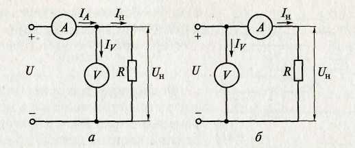
Figure: .1. Circuits for measuring power according to the readings of a voltmeter and ammeter for small (a) and large (b)load resistances
devices; the need to make calculations; low accuracy due to the summation of the instrument error.
Power R x , calculated from the readings of the instruments (Fig.1a), has the form
It is greater than the actual value of the power consumed in the load P n by the value of the power consumption of the voltmeter R v , i.e., P n \u003d R x - R v .
The error in determining the power in the load is the less, the more input impedance voltmeter and less load resistance.
Power R x , calculated according to the readings of the devices (Fig. 1, b),we have the form
It is greater than the actual value of the power consumption of the load by the value of the power consumption of the ammeter R AND . The methodical error is the less, the lower the input resistance of the ammeter and the higher the load resistance.
Compensation method. This method is used when a high accuracy of power measurement is required. The compensator measures the load current and the voltage drop across the load in turn. The measured power is determined by the formula
P= U n I n . (4)
In direct measurement, active power is measured by electromechanical (electrodynamic and ferrodynamic systems), digital and electronic wattmeters.
Electrodynamic wattmeters are used as portable devices for accurate power measurements (class 0.1 ... 2.5) in DC and AC circuits with a frequency of up to several thousand hertz.
Ferrodynamic panel voltmeters are used in AC circuits of industrial frequency (class 1.5 ... 2.5).
In a wide frequency range, digital wattmeters are used, the basis
make up various power converters (for example, thermoelectric), DCT, microprocessor and central control center. In digital wattmeters, automatic selection of measurement limits, self-calibration and an external interface are provided.
Special and electronic wattmeters are also used to measure power in high-frequency circuits.
Reactive power meters (varmeters) are used to measure reactive power at low frequencies, in which, by using special schemes, the deviation of the moving part of the electrodynamic MI is proportional to the reactive power.
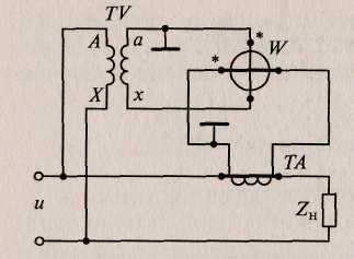
The inclusion of electromechanical wattmeters directly into the electrical circuit is permissible at load currents not exceeding 10 ... 20 A, and voltages up to 600 V. Power measurement at high load currents and in high voltage circuits is performed by a wattmeter with measuring current transformers TAand voltage TV(fig..2).
Measurement of active power in three-phase current circuits.Method of one wattmeter. This method is used only in a symmetrical system with a uniform phase load, the same phase angles between the vectors I and U and with full symmetry of voltages (fig..3).
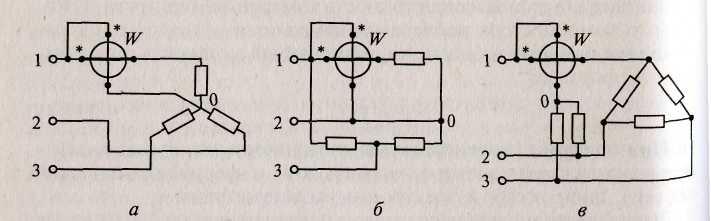
Fig. 3. Schemes for connecting a wattmeter to a three-phase three-wire circuit with full symmetry of the load connection:
and- a star; b -triangle; in ~ -with artificial zero point
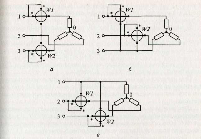
Fig. 4. Schemes for connecting two wattmeters in a three-phase circuit: and- in the 1st and 3rd; b- in the 1st and 2nd; in- in the 2nd and 3rd
In fig. .3, andthe load is star-connected and the zero point is available. In Fig. 3, bthe load is delta-connected, the wattmeter is in phase. In fig. .3, inthe load is delta connected to an artificial zero point. An artificial zero point is created using two resistors, each of which is equal to the resistance of the voltage winding circuit of the wattmeter (usually indicated in the data sheet for the wattmeter).
The readings of the wattmeter will correspond to the power of one phase, and the power of the entire three-phase network in all three cases of switching on the device will be equal to the power of one phase multiplied by three:
P \u003d3 P w
Method of two wattmeters. This method is used in a three-phase three-wire circuit, regardless of the connection scheme and the nature of the load, both with symmetry and with asymmetry of currents and voltages. Asymmetry is a system in which the powers of the individual phases are different. The current windings of the wattmeters are connected to any two phases, and the voltage windings are connected to line voltages (Fig. 4).
The apparent power can be expressed as the sum of the readings of the two wattmeters. So, for the circuit shown in Fig. 4, and,
where 1 is the phase angle between the current I 1 and line voltage U 12, 2 - phase angle between current I 3 and line voltage U 32 . In a particular case, with a symmetric voltage system and the same phase load 1, \u003d 30 ° - and 2 \u003d 30 ° - , the readings of the wattmeters will be:
With active load ( \u003d 0), the readings of the wattmeters will be the same, since P W ] = P W 2 IUcos30 °.
With a load with a shear angle cp \u003d 60 °, the readings of the second wattmeter are zero, since P W 2 = IUcos (30 ° + ) \u003d IUcos (30 ° + 60 °) \u003d 0, and in this case the power of the three-phase circuit is measured with one wattmeter.
With a load with a shift angle \u003e 60 °, the power measured by the second wattmeter will be negative, since (30 ° + ) is greater than 90 °. In this case, the moving part of the wattmeters will turn in the opposite direction. For counting, it is necessary to change the phase of the current in one of the wattmeter circuits by 180 °. In this case, the power of the three-phase current circuit is equal to the difference between the readings of the wattmeters
Three watt meter method. To measure the power of a three-phase circuit with an unbalanced load, three wattmeters are turned on, and the total power in the presence of a neutral wire will be equal to the arithmetic sum of the readings of three wattmeters. In this case, each wattmeter measures the power of one phase, the readings of the wattmeter, regardless of the nature of the load, will be positive (the parallel winding is switched on to the phase voltage, that is, between the linear wire and zero). If the zero point is not available and neutral wire is absent, then parallel circuits of devices can form an artificial zero point, provided that the resistances of these circuits are equal to each other.
Measurement of reactive power in single-phase and three-phase circuits.Despite the fact that reactive power does not determine either the work performed or the energy transmitted per unit of time, its measurement is also important. The presence of reactive power leads to additional losses of electrical energy in transmission lines, transformers and generators. Reactive power is measured in reactive volt-amperes (var) both in single-phase and three-phase three- and four-wire alternating current circuits by electrodynamic and ferrodynamic or specially designed wattmeters for measuring reactive power. The difference between a reactive wattmeter and a conventional wattmeter is that it has a complicated parallel circuit to obtain a phase shift of 90 °
between the vectors of current and voltage of this circuit. Then the deviation of the moving part will be proportional to the reactive power R r = UIsin . Reactive wattmeters are mainly used for laboratory measurements and verification of reactive meters.
The reactive power in a three-phase symmetrical circuit can also be measured with an active wattmeter: for this, the current coil is connected in series to phase A, the voltage coil between phases B and C.
Power measurement in high frequency circuits.For this purpose, both direct and indirect measurements can be used, and in some cases, indirect measurements may be preferable, since sometimes it is easier to measure the current and voltage across the load than directly power. Direct measurement of power in high and high frequency circuits is performed by thermoelectric, electronic wattmeters, Hall effect-based wattmeters, and digital wattmeters.
Indirect measurements are carried out using an oscilloscope method. It is mainly used when the circuit is powered by non-sinusoidal voltage, at high frequencies, low-power voltage sources, etc.
Energy measurement in single-phase and three-phase circuits.Energy is measured by electromechanical and electronic electricity meters. Electronic meters of electrical energy have better metrological characteristics, greater reliability and are promising means of measuring electrical energy.
4. Measurement of phase and frequency
The phase characterizes the state of the harmonic signal at a certain point in time t. Phase angle at the initial moment of time (origin), i.e. at t = 0, called zero(initial) phase shift.The phase difference is usually measured between current and voltage or between two voltages. In the first case, they are more often interested not in the phase angle itself, but in the value of cos or power factor. Cos is the cosine of the angle by which the load current leads or lags behind the voltage applied to this load. Phase Shift two harmonic signals of the same frequency are called the modulus of the difference between their initial phases \u003d | 1 - 2 |. The phase shift does not depend on time if the initial phases 1 and 2 remain unchanged. The phase difference is expressed in radians or degrees.
Phase angle measurement methods.These methods depend on the frequency range, signal level and shape, the required accuracy and the availability of measuring instruments. Distinguish between indirect and direct changes in the phase angle.
Indirect measurement. This measurement of the phase angle Between the voltage U and current I in load in single-phase circuits
carried out using three devices - a voltmeter, an ammeter and a wattmeter (Fig. 5). The angle is determined by calculation from the found value of cos:
![]()
The method is usually used at industrial frequency and provides low accuracy due to the methodological error caused by the devices' own consumption, it is quite simple, reliable, and economical.
In a three-phase symmetrical circuit, the cos value can be determined by the following measurements:
power, current and voltage of one phase;
measurement of active power by the method of two wattmeters;
measurement of reactive power by the method of two wattmeters with an artificial neutral point.
Among the oscillographic methods for measuring the phase, the methods of linear sweep and ellipse are most widely used. The oscillographic method, which allows you to observe and record the signal under investigation at any time, is used in a wide frequency range in low-power circuits with rough measurements (5 ... 10%). The linear sweep method involves the use of a two-beam oscilloscope, on the horizontal plates of which a linear sweeping voltage is applied, and on the vertical plates - voltage, between which the phase shift is measured. For sinusoidal curves on the screen, we get an image of two voltages (Fig. 6, and)and according to the measured segments AB and AC, the angle of shift between them is calculated
where AB is the segment between the corresponding points of the curves when they pass through zero along the axis X; АС - a segment corresponding to the period.
Measurement error x depends on the sampling error and phase error of the oscilloscope.
If, instead of a linear sweep, a sinusoidal sweeping voltage is used, then the Lissajous figures obtained on the screen at equal frequencies give the shape of an ellipse on the oscilloscope screen (Fig. 6b). Shear angle x \u003d arcsin (AB / VG).
This method allows you to measure x within 0 90 about without determining the sign of the phase angle.
The measurement error x is also determined by the reading error
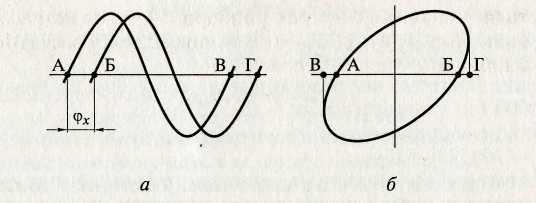
Fig..6. Curves obtained on the screen of a dual-beam oscilloscope: with a linear (and)and sinusoidal (b) sweep
and discrepancies in the phase shifts of the channels X and Y oscilloscope.
The use of an AC compensator with a calibrated phase shifter and an electronic oscilloscope as an indicator of phase equality allows a fairly accurate measurement of the phase angle. The measurement error in this case is determined mainly by the error of the used phase shifter.
Direct measurement. Direct measurement of the phase shift angle is carried out using electrodynamic, ferrodynamic, electromagnetic, electronic and digital phase meters. The most frequently used electromechanical phase meters are electrodynamic and electromagnetic ratiometric phase meters. The scale for these devices is linear. They are used in the frequency range from 50 Hz to 6 ... 8 kHz. Accuracy classes - 0.2; 0.5. They are characterized by a high power consumption 1 (5 ... 10 W).
In a three-phase symmetrical circuit, the measurement of the phase angle or cos is carried out by single-phase or three-phase phase meters.
Digital phase meters are used in low-power circuits in the frequency range from Hz to 150 MHz, accuracy classes - 0.005; 0.01; 0.02; 0.05; 0.1; 0.5; 1.0. In electronic counting digital phase meters, the phase shift between two voltages is converted into a time interval filled with pulses of a stable frequency with a certain period, which are counted by an electronic pulse counter. The components of the errors of these devices: discrete error, error of a stable frequency generator, an error that depends on the accuracy of the formation and transmission of the time interval.
Frequency measurement methods.Frequency is one of the most important characteristics of a batch process. It is determined by the number of complete cycles (periods) of signal change per unit of time. The range of frequencies used in technology is very large and ranges from fractions of hertz to tens. The entire frequency spectrum is divided into two ranges - low and high.
Low frequencies: infrasonic - below 20 Hz; sound - 20 ... 20,000 Hz; ultrasonic - 20 ... 200 kHz.
High frequencies: high - from 200 kHz to 30 MHz; ultra-high - 30 ... 300 MHz.
Therefore, the choice of the frequency measurement method depends on the range of measured frequencies, the required measurement accuracy, the magnitude and shape of the voltage of the measured frequency, the power of the measured signal, the availability of measuring instruments, etc.
Direct measurement. The method is based on the use of electromechanical, electronic and digital frequency meters.
Electromechanical frequency meters use a measuring mechanism of electromagnetic, electrodynamic and ferrodynamic systems with a direct reading of the frequency on the scale of a ratiometric meter. They are simple in design and operation, reliable, and have a fairly high accuracy. They are used in the frequency range from 20 to 2500 Hz. Accuracy classes - 0.2; 0.5; 1.0; 1.5; 2.5.
Electronic frequency meters are used for measurements in the frequency range from 10 Hz to several megahertz, with input signal levels of 0.5 ... 200 V. They have a large input impedance, which ensures low power consumption. Accuracy classes - 0.5; 1.0 and below.
Digital frequency meters are used for very accurate measurements in the range 0.01 Hz ... 17 GHz. The sources of error are the error from the discreteness and instability of the crystal oscillator.
Bridge method. This frequency measurement method is based on the use of frequency-dependent AC bridges supplied with the voltage of the measured frequency. The most common bridge circuit for frequency measurement is a capacitive bridge. The bridge frequency measurement method is used to measure low frequencies in the range of 20 Hz ... 20 kHz, the measurement error is 0.5 ... 1%.
Indirect measurement. The method is carried out using oscilloscopes: by interference figures (Lissajous figures) and circular sweep. The methods are simple, convenient and accurate enough. They are used in a wide frequency range of 10 Hz ... 20 MHz. The disadvantage of the Lissajous method is the complexity of decoding the figures when the ratio of figures is more than 10 and, therefore, the measurement error increases due to the establishment of the true frequency ratio. With the circular sweep method, the measurement error is mainly determined by the quantization error of the fundamental frequency.
METHODS AND TOOLS FOR MEASURING THE PARAMETERS OF THE MEASURING CIRCUITS