Electric motor - how an electric motor works
The rotating part of the machines - armature 9 (Figure 1.1) consists of core 7, winding 8 and collector 5.
The core is cylindrical. It is assembled from rings or segments of electrical steel sheet, on the outer surface of which grooves are stamped. Copper wire sections fit into the grooves of the core. The ends of the sections, which are brought out to the collector and are soldered to its plates, form a closed armature winding.
The principle of the generator. The simplest generator can be represented as a coil rotating in a magnetic field (Fig. 1.4, a, b). The ends of the loop are brought out to two collector plates. Fixed brushes are pressed against the collector plates, to which an external circuit is connected.
The principle of operation of the generator is based on the phenomenon electromagnetic induction... Let the coil be set in rotation from an external drive motor PD. The conductors of the active part of the loop cross the magnetic field and EMF e 1 and e 2 are induced in them according to the law of electromagnetic induction, the direction of which is determined by the right hand rule. When the coil rotates in the clockwise direction in the upper conductor located under the North Pole, the EMF is directed away from us, and in the lower, located under the South Pole, towards us. In the course of the loop, the EMF add up, the resulting EMF e \u003d e 1 - e 2.
If the external circuit is closed, then a current will flow through it, directed from the lower brush to the consumer and from him to the upper brush. The bottom brush turns out to be the positive terminal of the generator, and the top one is negative. When the turn is turned by 180 °, the conductors from the zone of one pole move to the zone of the other pole and the direction of the EMF in them changes to the opposite. At the same time, the upper collector plate comes into contact with the lower brush, and the lower - with the upper one, the direction of the current in the external circuit does not change. Thus, the collector plates not only provide the connection of the rotating coil with the external circuit, but also act as a switching device, i.e., they are the simplest mechanical rectifier. In the absence of a load (with an open external circuit of the generator), the mode takes place idle move generator. In this case, only the amount of mechanical energy is required from the diesel or turbine, which is necessary to overcome friction and compensate for other internal energy losses in the generator. With an increase in the load of the generator, i.e., the given electrical power P el, the current i passing through the conductors of the armature winding and the braking moment M created by it increase.Therefore, the mechanical power P mx, which the generator must receive from the diesel or turbine, must also be increased accordingly in order to continue normal operation.
Thus, the more electrical energy is consumed, for example, by the electric motors of a diesel locomotive from a diesel generator, the more mechanical energy it takes from the diesel engine rotating it and the more fuel must be supplied to the diesel engine.
From the operating conditions of the electric generator considered above, it follows that it is characteristic of it: coincidence in the direction of the current i and e. d. with e in the conductors of the armature winding; this indicates that the machine is giving electrical energy; the emergence of an electromagnetic braking torque M, directed against the rotation of the armature; from this follows the need for the machine to receive mechanical energy from the outside.
The principle of the electric motor. In principle, the electric motor is designed in the same way as the generator. The simplest electric motor is a coil located on the armature, which rotates in the magnetic field of the poles. The coil conductors form the armature winding. If you connect the coil to a source of electrical energy, for example to electrical network 6, then for each of its conductors will begin to pass electricity i. This current, interacting with the magnetic field of the poles, creates electromagnetic forces F. The force F will act on the conductor located under the South Pole, directed to the right, and the force F, directed to the left, will act on the conductor lying under the North Pole. As a result of the combined action of these forces, an electromagnetic torque M is created, directed counterclockwise, which drives the armature with the conductor into rotation with a certain frequency n. If you connect the armature shaft to any mechanism or device (wheelset of a diesel or electric locomotive, machine tool, etc. ), then the electric motor will drive this device into rotation, i.e., give it mechanical energy. In this case, the external moment M vn created by this device will be directed against the electromagnetic moment M.
Let us find out why electrical energy is consumed during the rotation of the armature of an electric motor operating under load. As it was found, when the armature conductors rotate in a magnetic field, e is induced in each conductor. d. s, direction of rotation e. etc. with. e, induced in the conductor located under the south pole will be directed away from us, and e. etc. with. e, induced in the conductor located under the north pole will be directed towards us. E. d. With. That is, those induced in each conductor are directed against the current i, that is, they prevent it from passing through the conductors.
In order for the current i to continue to pass through the armature conductors in the same direction, that is, so that the electric motor continues to work normally and develop the required torque, it is necessary to apply an external voltage U to these conductors, directed towards the e. etc. with. and larger than the total e. etc. with. E induced in all series-connected conductors of the armature winding. Therefore, it is necessary to supply electrical energy to the electric motor from the network.
In the absence of a load (external braking torque applied to the motor shaft), the electric motor consumes a small amount of electrical energy from an external source (network) and a small idle current passes through it. This energy is used to cover the internal power losses in the machine.
As the load increases, the current consumed by the electric motor and the electromagnetic torque it develops increase. Consequently, an increase in the mechanical energy given off by the electric motor when the load increases, automatically causes an increase in the electricity it takes from the source.
From the operating conditions of the electric motor considered above, it follows that it is characteristic of it:
coincidence in the direction of the electromagnetic moment M and the rotation frequency n; this characterizes the return of mechanical energy by the machine; the appearance in the conductors of the armature winding e. etc. with. e, directed against the current i and the external voltage U. This implies the need for the machine to receive electrical energy from the outside.
The collector (fig. 1.3) is made up of wedge-shaped copper plates, isolated from each other, and the body 3 micanite gaskets 2 forming a cylinder assembly that is attached to the armature shaft.
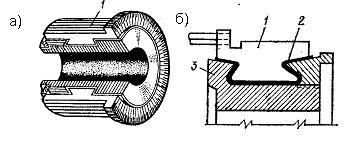
Figure 1.3 collector arrangement
Reversibility principle electric cars. Considering the principle of operation of the generator and the electric motor, we found that they are arranged in the same way and that there is much in common in the basis of the operation of these machines. The process of converting mechanical energy into electrical energy in the generator and electrical energy into mechanical energy in the engine is associated with the induction of e. etc. with. in the conductors of the armature winding rotating in a magnetic field and the occurrence of electromagnetic forces as a result of the interaction of the magnetic field and conductors with current. The difference between a generator and an electric motor lies only in the mutual direction of e. d. with, current, electromagnetic torque and speed.
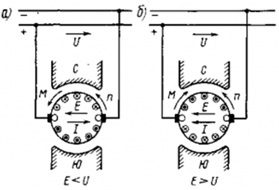
Figure: 68. Direction of e. etc. with. E, current I, armature rotation frequency n and electromagnetic moment M during operation of an electric machine direct current in motor (a) and generator (b) modes
Summarizing the considered processes of operation of the generator and electric motor, it is possible to establish the principle of reversibility of electrical machines. According to this principle, any electric machine can operate as a generator and an electric motor and switch from generator mode to motor mode and vice versa.
To clarify this situation, consider the operation of a direct current electric machine under various conditions. If the external voltage U is greater than the total e. etc. with. G. in all series-connected conductors of the armature winding, then the current I will flow in the one indicated in Fig. 68, and the direction and the machine will operate as an electric motor, consuming electrical energy from the network and giving mechanical energy. However, if, for whatever reason, e. etc. with. E becomes greater than the external voltage U, then the current I in the armature winding will change its direction (Fig. 68, b) and will coincide with e. etc. with. E. In this case, the direction of the electromagnetic moment M will also change, which will be directed against the rotation frequency n. Coincidence in the direction of e. etc. with. E and current I means that the machine began to give electrical energy to the network, and the appearance of the braking electromagnetic moment M indicates that it must consume mechanical energy from the outside. Therefore, when e. etc. with. E induced in the conductors of the armature winding becomes more stress network U, the machine switches from motor operation to generator mode, i.e. when E< U машина работает двигателем, при Е > U - generator.
The transfer of an electric machine from a motor mode to a generator mode can be carried out in various ways: by reducing the voltage U of the source to which the armature winding is connected, or by increasing the e. etc. with. E in the armature winding.
3. CLASSIFICATION, OPERATING PRINCIPLE, DESIGN,
BASIC CHARACTERISTICS, REGULATION PRINCIPLES
REVERSIBILITY OF AC ELECTRIC MACHINES.
Cars alternating current... Description classification.
An electrical machine has a stator and a rotor separated by an air gap (Fig. 1 and Fig. 2). Its active parts are the magnetic circuit and windings. All other parts are structural, providing the necessary rigidity, strength, rotation, cooling, etc.
The magnetic circuit of the machine, through which the alternating magnetic flux is closed, is made laminated - from sheets of electrical steel, like that of a transformer. If the flux is constant, then the magnetic circuit can be made massive; in this case, it can also carry out structural functions, i.e., serve as an element that ensures the strength of a given part of the machine (stator or rotor).
Since in parts of electrical machines the magnetic flux is closed along complex contours other than rectilinear ones, isotronic cold-rolled steel is usually used in them. Only for the manufacture of poles of synchronous machines and large DC machines is sometimes used anisotropic cold-rolled steel, since in the poles the direction of the magnetic lines coincides with the direction of rolling, in which the magnetic permeability is very high. Stator and rotor cores asynchronous machines and armatures of DC synchronous machines are stamped from isotronic coiled cold-rolled steel, which makes it possible to obtain savings of the order of 10-15% when cutting in comparison with sheet steel, as a result of which sheet steel is used very rarely.
Electrical term "anchor" much older than the word electrical engineering. In the era of great geographical discoveries and the development of navigation in the world's oceans, there was an urgent need for magnetic compasses, the main part of which was a magnetic needle. These hands were made of iron and were magnetized with natural magnets. There were simply no others.
Good magnetization required good magnets. To enhance the effect of natural magnets, they were reinforced with iron, attaching it to the stone using non-magnetic frames made of copper, silver and even gold. All this was decorated with stylized figurines, ornaments or inscriptions.
Magnets were expensive. The set of the magnet also included a removable iron bar, which was "stuck" to the poles of the magnet. This block had on one side a ring, a hook or a decorative copy of a sea anchor for hanging a kettlebell. The force of holding this block by a magnet could always be measured by the weight of the weights placed in the cup. The very same bar with a hook was called the "magnet anchor".
With the invention of electromagnets in 1825, the method of measuring their strength has not changed. So, for example, in the preamble of his work, published in 1838 in St. Petersburg under the title "On the attraction of electromagnets", Russian academicians B.S. Jacobi and E.H. Lenz directly wrote it down: "The force of attraction was determined by the weight of the weights, which were applied until the anchor came off."
Electromagnets could already create powerful magnetic fields... American scientist J. Henry created an electromagnet, the anchor of which was able to hold a load weighing a ton. But this is not his main merit as an engineer. He put the anchor of the electromagnet on a hinge and made it hit the bell with attraction. This is how the first electromagnetic bell appeared.
By adapting the contacts to a moving armature, the American received a hitherto unknown device - a relay, a device for automatic switching of electrical circuits by a signal from the outside, which allows telegraph signals to be transmitted over almost any distance.
In modern electromagnetic relays, the moving part of the magnetic circuit is still called an anchor, although it has no external resemblance to the restraining device of a ship in the roadstead.
J. Henry's inventive thought did not stop there. He made a magnetic circuit with a coil and installed it horizontally, like a beam of a laboratory analytical balance. When the device (armature) swings, the contacts fixed at the ends of the rocker arm periodically touched the terminals of two galvanic cells that supplied the coil with currents of different directions. Accordingly, the rocker, swinging, was attracted to the two permanent magnets that entered the system.
The installation worked continuously, giving the armature 75 oscillations per minute. This is how one of the first designs of an electric motor with a reciprocating motion appeared. However, it was not difficult to turn it into a rotational one for that time.
Henry wrote: “I managed to set in motion a small machine with a force that has not yet found application in mechanics, I am talking about magnetic attraction. I do not attach of great importance this invention, for in its present form it is only a physical toy. However, the possibility is not excluded that with the further development of the principle, this can be used for practical purposes. "
Machines with a reciprocating motion then did not gain widespread acceptance, although quite workable designs were proposed by W. Clark, C. Page and others. An electric motor with a rotating armature turned out to be technologically more convenient to use.
Then came the era of three-phase alternating current. No one called the rotating units of AC motors an anchor, and this was true. How not to call a rotating magnetic field a vortex, but a rotating part rotor? But in DC machines (both motors and generators), the terminology remains the same. The anchor rotates, and the pole piece is called a shoe, a word that can be found now only in fairy tales of the 18th century.
Maybe technology should be changed? Let's not rush. Nowadays, multiphase linear electric motors for monorail trains are gaining popularity. Here, a tightly reinforced monorail is used as a rotor, and windings installed on the magnetic circuit of a rapidly rushing electric locomotive are used as a stator (from the Latin - standing motionless). And is it necessary to change the established concepts, at the risk of introducing even greater confusion?
Page 1
The armature of the electric motor consists of a shaft on which a core made of varnished electrical steel with a thickness of Ø 5 mm, with grooves for winding, and a collector are pressed. The armature winding is two-layer with a diametrical pitch made of PELSHKO wire. The collector is assembled from red copper plates, isolated from each other by micanite gaskets. Reinforcement of the collector is carried out on plastic and is carried out with the help of steel rings, which are placed in dovetail grooves before pressing the collector. To prevent shorting of the collector plates, the rings are insulated with fiberglass tape before laying. As a result of reinforcement, the strength of the collector is increased. The winding is connected to the collector in the same way as in DC motors.
The electric motor armature is disassembled in the following sequence: the tapered roller 4 (see Fig. 82) is unscrewed from the armature shaft; using a puller, the bearing 5 and the fan 8 are pressed; remove oil deflectors 2; replace unusable bearings, remove the winding, wind a new one, assemble the armature and the electric motor. The horizontal alignment of the armature is carried out by the bearing cap (plug) 19.
The armature of the electric motor consists of a package of transformer steel plates, an anchor winding, a fan (impeller) and a collector. The armature collector has copper plates (lamellas), between which micanite gaskets are placed.
| Rotation scheme for rubbing. |
The motor armature consists of a package of transformer steel plates, an anchor winding, a fan (impeller) and a collector.
The armature of the electric motor rotates on two bearings located in the end shields. There is a centrifugal fan on the armature shaft for cooling the electric motor. Air is drawn in through the manifold-side end-shield louvers, passes through the machine and is discharged by the fan through the upper end-shield grilles.
The electric motor armature rotates in two self-aligning bronze-graphite bushings impregnated with turbine oil.
The anchor of the electric motor is assembled from sheets 7 of the same shape as the anchor of the DP-4 engine. The coils 6 of the armature winding are wound on the teeth of the core and are isolated from them by strips of electric cardboard. The three lead-out ends of the armature coils are interconnected, and the other three are soldered to three collector plates molded into plastic.
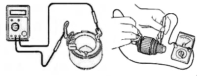
The motor armature refers to the rotating part on which dirt collects and deposits form. In case of malfunctions, you can carry out diagnostics at home visually and using a multimeter. There should be no chips, scratches or cracks on the rubbing surfaces. If any are found, measures are taken to eliminate them.
Typical malfunctions
The motor armature is not subject to wear during normal operation. Replace only the brushes, measuring the permissible length. But with prolonged loads, the stator windings begin to heat up, which leads to the formation of carbon deposits.
Due to mechanical influences, the armature of the electric motor can be skewed if the bearing assemblies are damaged. The engine will run, but the gradual wear of the fins or fins will lead to its permanent failure. But to save expensive equipment, it is often enough to carry out preventive repairs and the device can be used for a long time.
The negative factors that affect the armature of the electric motor include moisture ingress on metal surfaces. Prolonged exposure to moisture and rust is critical. Due to red accumulations and dirt, friction increases, this increases the current load. The contact parts get hot, the solder can flake off, creating a periodic spark.
The service center can help, but this will require certain costs. You can cope with a breakdown yourself, having familiarized yourself with the question: how to check an electric motor anchor at home. For diagnostics, you will need a device that measures resistance and tools.
How is a malfunction diagnosed?
Checking the motor armature begins with determining the fault itself. Complete failure of this unit occurs due to scattered collector brushes, destruction of the dielectric layer between the plates, as well as due to a short circuit in electrical circuit... In case of sparking inside the device, it is concluded that the current collectors are worn or damaged. 
The sparking of the brushes begins due to the appearance of a gap at the point of contact with the collector. This is preceded by a fall of the device, a high load on the shaft during jamming, as well as a violation of the integrity of the solder on the winding terminals.
A malfunction on a running motor manifests itself in typical conditions:
- Arcing is the main symptom of a malfunction.
- Rumble and friction when the anchor rotates.
- Perceptible vibration during operation.
- Change of direction of rotation when the anchor passes the trajectory less than a revolution.
- The smell of melting plastic or strong heating of the case.
What to do if the listed deviations appear in the work?
The frequency of rotation of the motor armature is kept constant. At idle speed, the malfunction may not appear. Under load, the friction is compensated for by an increase in current flowing through the windings. If deviations in the work of the grinder, drill, starter become noticeable, then you need to remove the voltage supply. 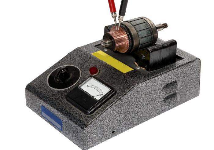
Continued use of the devices may result in a fire or electric shock to a person.The first step is to inspect the product case, evaluate the wiring for integrity, the absence of melted parts and damage to the insulation. The temperature of all parts of the device is checked by touch. They try to rotate the anchor by hand, it should move easily, without jamming. If the mechanical parts are intact and there is no contamination, proceed to disassembly.
Internal diagnostics
The armature winding of the electric motor should not have carbon deposits, dark spots, similar to the consequences of overheating. The surface of the contact parts and the gap area must not be littered. Small particles reduce motor power and increase current. Do not disassemble devices with a plug connected to the network for the safety of work. 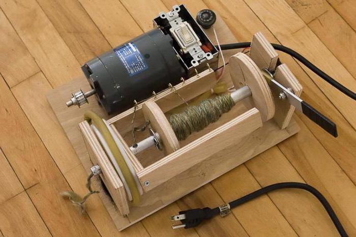
It is recommended to film the disassembly process in order to avoid difficulties in the reverse process. Or you can write down each step of your actions on a piece of paper. Some wear of brushes and lamellas is allowed. But if you find scratches, you should find out the reason for their origin. Perhaps this was due to a crack in the case, which can only be noticed under load.
Work with an ohmmeter
Sincere could occur due to the loss of electrical contact in one of the lamellas. To measure resistance, it is recommended to install the probes on the side of the current collectors. Rotating the motor shaft, watch the dial readings. There should be zero values \u200b\u200bon the screen. If numbers slip even in a few ohms, then this speaks of soot. When an infinite value appears, an open circuit is judged.
Regardless of the results, the next step is to check the resistance between each adjacent lamellae. It should be the same for every measurement. In case of deviations, it is necessary to inspect all the connections of the coils and the contact surface of the brushes. The brushes themselves should wear evenly. In case of chips and cracks, they must be replaced. 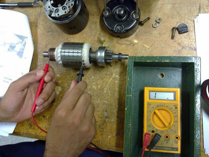
The coils are connected to the core by wire that may have peeled off. Solder often does not withstand impacts from falls. At the starter, the current through the contacts can reach 50A, which leads to the burnout of poor-quality connections. The places of damage are determined by external examination. If no malfunction is found, then the resistance is measured between the lamella and the coil itself.
If there is no ohmmeter?
In the absence of a multimeter, you will need a 12 volt power supply and a lamp for the corresponding voltage. Any car enthusiast will have no problems with such a set. The plus and minus terminals are connected to the plug of the electrical appliance. An incandescent lamp is placed in the gap. The result is observed visually.
The armature shaft is rotated by hand, the lamp burns without jumps in brightness. If attenuation is observed, a faulty motor is judged. Most likely happened turn-to-turn closure... Complete disappearance of the glow indicates an open circuit. The reasons may be non-contact of the brushes, breakage in the winding or lack of resistance in one of the lamellas.
How to "revive" a faulty device?
Repair of the electric motor armature begins only after complete confidence in the malfunction of the unit. Scratches and chips on the lamellas are removed with a circular surface groove. Carbon deposits and soot can be removed with cleaning agents for electrical contact connections. Broken bearings are repressed and replaced with new ones. It is important to keep the shaft balanced during assembly. 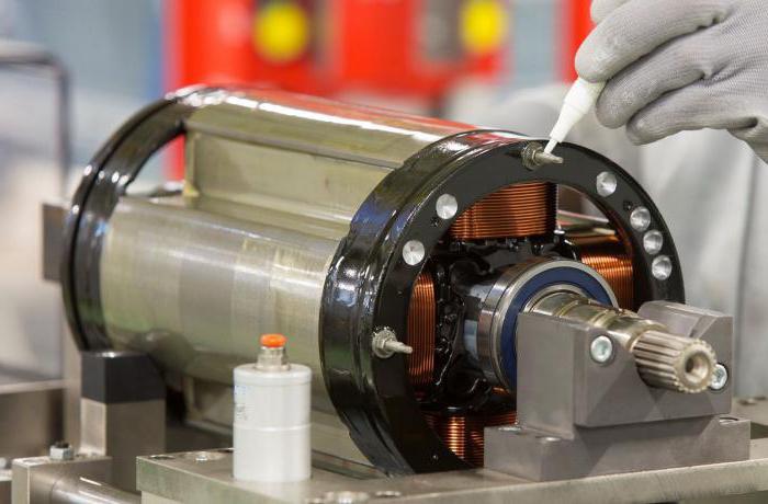
The rotation should be light and quiet. The damaged insulation is restored, you can use ordinary electrical tape. It is best to re-solder connections that are suspicious. In case of problems with the armature coils, it is recommended to resort to rewinding, which you can do yourself.
Recovery of coils
You can rewind the anchor of the electric motor in a garage, only you need to be careful when applying each turn. Copper wiring is selected similarly wound. The cross section must not be changed, this will lead to a violation of the high-speed modes of the engine Dielectric paper is required to separate the windings. The coils are filled with varnish at the end.
You will need a soldering iron and skills in using it. The joints are treated with acid, rosin is used to apply tin-lead solder. When dismantling the old winding, count the number of turns and apply a similar amount of new winding.
The housing must be free of old varnish and other inclusions. A file, sandpaper or burner is suitable for this. Sleeves are made for the anchor, the material is electrical cardboard. The resulting blanks are placed in the grooves. Wound coils should be made with right turns. The conclusions from the side of the collector are rewound with a nylon thread. 
Each wire is soldered to the corresponding lamella. The assembly should end with the next measurements of the resistance of the contact connections. If everything is normal and not, you can check the operation of the electric motor under voltage.
Collector motors stand in washing machines (but not in all models), vacuum cleaners, power tools, children's toys, etc. Their main distinguishing feature is the presence of fixed stator windings and windings on the shaft (armature), which are energized by means of a collector and graphite brushes ...
If yours is broken or junk motor in a power tool and other devices, then do not rush to throw it away, because in most cases it can be quickly and inexpensively repaired with your own hands. You will learn how to identify and fix the problem later in this article.
Before you start looking for a reason in electric motors, first check the serviceability of the power cord, power buttons and, if there are start-adjusting devices.
How to check a collector motor - the most common breakdowns
To identify and eliminate faults you will have to disassemble the power tool itself or the electric motor of other household devices. Just before you start disassembling, pay attention to sparking in the contact-brush mechanism. 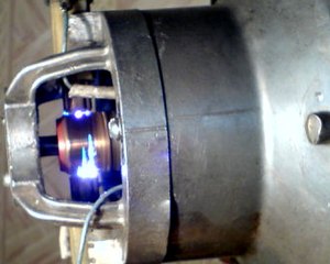 If it is high (as in the figure for the lower brush), then this may indicate wear or poor contact of the brushes, less often an inter-turn circuit in the collector.
In most cases Brush wear and blackening of the collector are the cause of damage to collector motors. Worn brushes must be replaced with new ones of the same shape and size, better of course with original ones. They change very simply - either you need to remove or move the latch or unscrew the bolt.  In some models, it is not the brushes themselves that change, but the assembly with the brush holder. Do not forget to connect a copper lead to the contact. If the brushes are intact, then stretch the springs pressing them.
If the contact part of the collector is darkened, then it must be cleaned with fine sandpaper (zero). 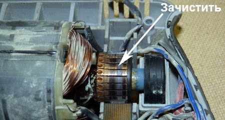
Sometimes, together with the contact of the brushes with the collector, a groove is formed. It must be turned on the machine.
In second place the number of faults is the wear of the bearings. The need to replace them in the power tool is evidenced by the beating of the cartridge and the increased vibration of the body during operation. How to check and replace bearings is described in detail in. In the most advanced cases, they begin to touch the armature and stator during rotation - at least you will have to change the armature.
How to check a collector motor - rare breakdowns
Much less often there is a break or burnout in the windings or in the places of their connection, melting or closure of the collector lamellas with graphite dust.
In most cases, this can be determined by external examination. Wherein pay attention to:
- The integrity of the windings.
- Blackening of the windings, either all or part of it.
- Reliability of contacts of leads of wires with collector lamellas. Solder if necessary.
- Is the space between the lamellas clogged with graphite dust? If so, clean it.
- The characteristic smell of burning wire insulation.
If found visual damage to the starter or armature winding, then they will need to be replaced with new ones or rewound.
But it is not always visually possible to determine damage to the windings, so you should use a multimeter for this purpose.
How to ring an electric motor with a multimeter
Turn on the multimeter in continuity mode or ohmmeter with a measurement range of 50-100 ohms. How to do it read a.
Sometimes there is a turn-to-turn closure in the winding, then it can be determined only with the help of a special device-device checking anchors.
Similar materials.