The vector of the magnetic field strength and its relationship with the vectors of induction and magnetization. Magnetic susceptibility and magnetic permeability of matter
Capacitive element
An example of a capacitive element is a flat capacitor - two parallel plates spaced a short distance from each other.
Voltage applied to the capacitive element:
Then the current in the capacitive element:
ic \u003d Imsin (ωt + 900), I m \u003d U m / X c, where X c \u003d 1 / (ω⋅C) is the capacitive resistance, measured in ohms and depends on the frequency.
1. The current in the capacitive element is phase ahead of the voltage applied to it, by 900.
2. The capacitive element provides a sinusoidal (alternating) current resistance, the modulus of which X c is inversely proportional to the frequency.
3. Ohm's law is fulfilled both for the amplitude values \u200b\u200bof current and voltage: \u003d Xc ⋅Im,
and for the effective values: Um \u003d XС IС.
Instantaneous power:
p \u003d U⋅I sin2ωt.
The instantaneous power on the capacitive element has only the variable component U⋅I⋅sin2ωt, changing with a double frequency (2ω).
The power periodically changes in sign - then positive, then negative. This means that during one quarter of periods, when p\u003e 0, energy is stored in the capacitive element (in the form of energy electric field), and during the other quarter periods when p< 0 , энергия возвращается в электрическую цепь.
Calculation of an unbranched electrical circuit sinusoidal current.
Power in linear circuits of sinusoidal current
In linear circuits of sinusoidal current, there are three types of power:
Active;
Reactive;
Active power Is the power of irreversible conversion of electrical energy into other types of energy in resistive circuit elements. In sources of electrical energy, the active power P is calculated by the formula: P \u003d U ⋅ I ⋅ cos φ, where φ is the phase angle between current and voltage.
In resistive elements, the active power is also determined by the formula: P \u003d I2⋅R.
Lecture 4. Analysis and calculation of magnetic fields
Magnetic field and its characteristics.
When an electric current passes through a conductor, a magnetic field is formed around it. It possesses energy, which manifests itself in the form of electromagnetic forces acting on moving electric charges, i.e. electricity... The magnetic field is formed only around moving electric charges, and its effect also applies only to moving charges. Magnetic and electric fields are inseparable and form a single electro-magnetic field. Any change in the electric field leads to the appearance of a magnetic field and, conversely, any change in the magnetic field is accompanied by the appearance of an electric field.
The main characteristics of the magnetic field are magnetic induction, magnetic flux, magnetic permeability, magnetic field strength.
Magnetic induction.
The intensity of the magnetic field, that is, its ability to perform work, is determined by a quantity called magnetic induction B. The stronger the magnetic field, the greater the induction it has. Those. magnetic induction is the power characteristic of the magnetic field. INcan be characterized by the density of the magnetic lines of force, that is, the number of lines of force passing through a unit of area located perpendicular to the magnetic field. Distinguish between homogeneous and non-uniform magnetic fields. In a uniform magnetic field, the magnetic induction at each point of the field has the same value and direction. A field in the air gap between opposite poles of a magnet or electromagnet can be considered uniform. Measurement unit of magnetic induction - tesla (T); 1 T \u003d 1 Wb / m 2.
Magnetic flux or the flux of the magnetic induction vector through the area S is called the value
where Ф - magnetic flux, Wb;
B - magnetic induction, T;
S - flat area, m 2;
α - angle between the direction of the normal n to the site and direction of induction IN;
Bn - vector projection IN to normal n.
SI unit of magnetic flux - weber (Wb), has the dimension B * s (volt-second). Measurement unit of magnetic induction - tesla (T); 1 T \u003d 1 Wb / m 2.
Magnetic permeability - physical quantitycharacterizing the magnetic properties of a substance. Magnetic permeability shows how many times absolute magnetic permeability of this material more magnetic constant. Numerically equal to the ratio absolute magnetic permeability μ a to magnetic constant μ 0 (μ \u003d μ a / μ 0).
The change in the force of interaction between conductors with current is due to a change in the intensity of the magnetic field caused by the size, shape of the wires, as well as the magnetic properties of the substance between the wires.
Depending on the properties of the medium, the value of μ can be greater than in vacuum (μ\u003e 1) or less (μ<1). Магнитная проницаемость воздуха и большинства веществ, за исключением ферромагнитных материалов, близка к единице, поэтому для них μ а ≈ μ 0 = 4л 10 -7 Г/м.
Magnetic field strength ... A vector quantity that is a quantitative characteristic of the magnetic field. Tension H does not depend on the magnetic properties of the medium. Magnetic induction and tension are related
H \u003d B / m a \u003d B / (mm about)
Consequently, in a medium with constant magnetic permeability, the induction of the magnetic field is proportional to its strength. The magnetic field strength is measured in ampere per meter (A / m).
The magnetic field of a conductor with current.
When current passes through a straight conductor, a magnetic field arises around it. The magnetic lines of force of this field are located in concentric circles, in the center of which there is a conductor with current. The direction of the magnetic field around the conductor with current is always in strict accordance with the direction of the current passing through the conductor. The direction of the magnetic field lines can be determined by gimbal rule. It is formulated as follows. If the forward movement of the gimbal is combined with the direction of the current in the conductor, then the direction of rotation of its handle will indicate the direction of the magnetic field lines around the conductor. For example, if the current passes through a conductor in the direction away from us beyond the plane, then the magnetic field arising around this conductor is directed clockwise. If the current flows through the conductor towards us, then the magnetic field around the conductor is directed counterclockwise. The greater the current passing through the conductor, the stronger the magnetic field arising around it. When the direction of the current changes, the magnetic field also changes its direction.
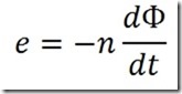
Electromagnetic induction - this is the phenomenon of the occurrence of a current in a closed conductor, when a magnetic flux passes through it.
Electromagnetic induction law (M. Faraday's law)
The electromotive force induced in a conductive loop is equal to the rate of change of the magnetic flux coupled to this loop.
![]()
In a coil that has n turns, the total EMF depends on the number of turns n:
The EMF direction is determined by right hand rule: the right hand is positioned so that the magnetic lines enter the palm, the thumb bent at a right angle is aligned with the direction of speed; then the extended four fingers will show the direction of the EMF.
Lenz's rule
The induction current arising in a closed loop with its magnetic field counteracts the change in the magnetic flux by which it is caused.
Magnetic circuits
When calculating permanent magnets, electromagnets, transformers, electric cars, relays, magnetic amplifiers, electrical measuring and other devices use the concept magnetic circuit .
Substances that can be magnetized are called magnets. Term magneticapplies to all substances when considering their magnetic properties.
Substances for which magnetic permeability less than one µ<1, называются diamagnetic or diamagnetic (bismuth, water, hydrogen, copper, glass), substances with µ\u003e 1 - paramagnetic orparamagnets (oxygen, platinum, tungsten, aluminum), and substances for which µ \u003e\u003e 1 - ferromagnets (iron, cobalt, cast iron, nickel).
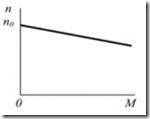
In diamagnets, as in paramagnets, the dependence B (H) (magnetization curve) is linear, the only difference is in the slope of the graph.
The magnetization curve shows the relationship between magnetic induction and magnetic field strength. For ferromagnets, this relationship is essentially nonlinear. The field induction in a magnetized ferromagnet first increases rapidly with an increase in the strength of the external magnetic field. Then the growth of the field induction slows down.
Magnetic circuit called a sequence of magnets through which the magnetic flux passes.
When calculating magnetic circuits an almost complete formal analogy with electrical circuits is used.
A similar mathematical apparatus also contains ohm's law , kirchhoff rules and other terms and patterns.
The magnetic circuit and the accompanying mathematical apparatus are used to calculate transformers, electrical machines, magnetic amplifiers, etc.
If the magnetic flux is excited in a magnetic circuit by permanent magnets, then such a circuit is called polarized.
A magnetic circuit without permanent magnets is called neutral. The magnetic flux in it is excited by the current flowing in the windings covering part or all of it.
Depending on the nature of the excitation current, a magnetic circuit of constant, alternating and pulsed magnetic fluxes is distinguished.
Magnetic circuits at constant fluxes
For a section of a magnetic circuit
Ф \u003d BS,
where Ф - magnetic flux, Wb;
B - magnetic induction, T;
S is a cross-section of a plot m 2.
Magnetic voltage drop on the section of the magnetic circuit with a length l equal to the product of the magnetic flux and the magnetic resistance R M of the section
U M \u003d H l\u003d FR M,
where H is the magnetic field strength, A;
l - average length of the section, m;
R M is the magnetic resistance of the site, 1 / H.
Plot magnetic resistance
R M \u003d l/ (µ r µ 0 S),
where µ r is the relative magnetic permeability of the area material;
µ 0 \u003d 4π 10 -7 - magnetic constant, H / m.
Example... Determine the magnetic resistance of the circuit section length l\u003d 0.1 m and section S \u003d 0.01 m 2, if µ r \u003d 5000.
![]() 1 / Mr.
1 / Mr.
Magnetomotive force (MDS)
where F is the magnetomotive force, A
I is the current in the winding, A;
w is the number of turns of the winding.
Ohm's law for a magnetic circuit
The magnetic flux for a section of the circuit is directly proportional to the magnetic voltage in this section.
Ф \u003d U m / R m
Kirchhoff's first law for a magnetic circuit
The algebraic sum of magnetic fluxes in the magnetic circuit unit is equal to zero
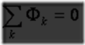 .
.
Kirchhoff's second law for a magnetic circuit
The algebraic sum of the magnetic voltage drops along a closed loop is equal to the algebraic sum MDS acting in the circuit
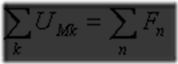 .
.
Lecture 5. Electrical machines and electromagnetic devices
Electric car - an electromagnetic device consisting of a stator and a rotor, and converting mechanical energy into electrical energy (generators) or electrical energy into mechanical energy (electric motors).
The principle of operation of electric machines is based on the laws of electromagnetic induction, Ampere and the phenomenon of a rotating magnetic field.
According to the law of electromagnetic induction, discovered by M. Faraday in 1831, an EMF E is induced in a conductor placed in a magnetic field and moving relative to it with a speed V, the direction of which is determined by the rule of the gimbal or the rule of the right hand.
According to Ampere's law, a force acts on a conductor with a current I, placed in a magnetic field, the direction of which is determined by the rule of the gimbal or the rule of the left hand.
Cars direct current
A DC machine has three main parts: inductor, armature and collector.
Inductor - the stationary outer part of the machine, designed to create a magnetic flux F. The inductor is a hollow cast steel cylinder, to which poles are attached from the inside - electromagnets powered by direct current.
Anchor - rotating interior of the machine. It consists of a steel cylindrical core and a winding of an insulated copper wire, in which, when it is crossed by a magnetic flux Φ, em is created. etc. with. E. On the same shaft with the armature, a collector is fixed, the purpose of which is mechanical rectification of sinusoidal variables. etc. with. (created in the conductors of the rotating armature winding) into a voltage constant in magnitude and direction, supplied to the external circuit using brushes applied to the collector.
Collector is the most complex part of a DC machine. In each section of the armature winding, a variable sinusoidal e is created. etc. with. Thanks to the collector e. etc. with. machine E, removed into the external chain through the brushes, is constant in magnitude and direction.
E. d. With. DC machine is proportional to the magnetic flux of the inductor and the speed of rotation of the armature.
Types of DC machines according to the excitation circuit
The excitation circuit is the power circuit of the inductor winding. The excitation circuit determines the basic properties and characteristics of the machine.
According to the excitation scheme, DC machines are divided into machines with independent excitement and self-excited machines .
In the car with independent excitement the inductor winding is powered by an external direct current source. A circuit with independent excitation (with electrically unconnected circuits of the armature and inductor) is used relatively rarely. Typically, in DC machines, both generators and motors, the armature and inductor circuits are electrically connected. In this case, the generators are self-excited: the inductor winding is powered by the armature current of the same machine.
Depending on the circuit by which the armature and inductor windings are electrically connected, a distinction is made between three types of DC machines, having in the generator and in the motor mode is significantly different characteristics and accordingly different areas of application: machines with parallel excitation (shunt); machines with series excitation (series) and machines with mixed excitement (compound).
IN parallel excitation machine the excitation winding is connected in parallel with the armature (in relation to the external circuit), and in the machine sequential excitation - consistently. Mixed Excitation Machine has parallel and series field windings, and usually the main winding is parallel.
Self-excitation in DC generators based on the use of the phenomenon of hysteresis in the steel of the poles of the inductor.
Independent excitation circuit
Parallel excitation circuit
Sequential excitation circuit
Mechanical characteristics of DC machines
Series Excited Motor
Parallel excitation motor
![]()
Mixed excitation motor
Applications of DC machines
Although modern electrification is mainly carried out with three-phase alternating current, DC machines, especially in motor mode, have a fairly wide application.
Generators are most often used in motor-generator converter installations to obtain direct current from alternating current for the purpose of supplying direct current motors and for other needs in factory and laboratory conditions.
Generators are also used on diesel locomotives of mainline railways, on ships, for DC electric welding, for lighting trains, as exciters for synchronous machines, etc.
Small-sized low-voltage generators (6-12 and 28 Volts) are widely used for lighting and charging batteries on airplanes and cars of all types.
In a number of cases, for special needs DC machines with very low power permanent magnets are used as tachogenerators (for measuring the speed of rotation of machines), as an inductor for testing insulation, in ignition machines in explosives, etc.
DC motors have good performance, have easy speed control over a wide range, but compared to motors alternating current have serious disadvantages: the need for a direct current source, design complexity and higher cost, the need for constant supervision due to the presence of a collector.
Serial excitation motors are more widely used than shunt motors. The sequential excitation motor is the basic type of traction motor. It has a large starting torque (proportional to the square of the amperage). The engine automatically adjusts to the track profile, changing the speed accordingly, which is essential for a traction engine. Trams all over the world are powered by serial DC motors.
Sequential excitation motors are widely used on suburban and mainline electrified railways, in the subway, in electrified factory and mine transport, in electric cars, etc.
Motors with mixed excitation (with a predominance of series winding) are used in trolleybuses and on main electrified railways with regenerative braking, that is, with energy transfer to the network on descents.
Motors with parallel excitation are used instead of asynchronous and synchronous ones where smooth speed control is required over a wide range, for example, in powerful rolling mills, in the textile industry, etc.
Electrical machine-building plants produce many types of DC machines with a wide range of power, voltage and rotation speed, in open, protected, closed and explosion-proof versions.
Asynchronous and synchronous motors (cars)
The nature of the magnetic field was clarified by Oersted, who in 1820 showed that a magnetic field is formed around a conductor with a current, the direction of which is determined by the "gimbal" rule. Ampere studied the dependence of the force of interaction between conductors with current on their configurations, establishing the law that received his name. So, two parallel conductors with currents flowing in the same direction interact with a force per unit length:
where  = 4
= 4 ... 10 -7 H / m is the absolute magnetic permeability of the vacuum, I 1 and I 2 are the currents flowing in the conductors, and g is the distance between the conductors. This formula is used to establish the basic electrical unit of the C system - the current strength (Ampere). With a current of one ampere, two conductors located at a distance of one meter from each other interact with a force of 2 10 -7 Newtons per meter. Conductors with oppositely directed currents repel. In a sense, formula (9) is an analogue of the Coulomb law.
Thus, it is possible to give a definition that a special type of matter is called a magnetic field, through which the interaction of electric currents or moving electric charges is carried out.
The magnetic field can be detected using a magnetic needle, which will be acted upon in the magnetic field by a pair of forces. The magnetic needle can be replaced with a current frame. It is characterized by the magnitude of the magnetic moment: p m = I . Sequal to the product of the current in the frame I by the area of \u200b\u200bthe frame S. The magnetic moment is a vector whose direction is determined by the rule of the right screw. In a magnetic field, a pair of forces acts on the frame with current, striving to establish the magnetic moment of the frame in the direction of the external magnetic field. In accordance with this, the force characteristic of the magnetic field B is introduced, called magnetic induction, which is equal to the ratio of the maximum moment of a pair of forces acting on a frame with a current in a magnetic field to the magnetic moment of this frame p m:
The magnitude of the magnetic induction in Tesla is measured. T \u003d N. m / A. m 2.
In a substance (magnet), the magnetic induction changes its value: B \u003d  In where - relative magnetic permeability, B 0 - magnetic induction of the field in vacuum. Value H \u003d B /
  called the strength of the magnetic field. Find the magnetic field created by any configuration of conductors, allows the law of Bio-Savart-Laplace. So the magnetic induction of the field created by an infinite conductor with current is equal to:
The direction of the induction vector is determined by the "gimbal" rule and coincides with the direction of the tangent to a circle of radius r, perpendicular to the current vector. In the center of a circular conductor with current, the induction is:
In an inductance coil containing N turns with a current, length l, induction is equal to:
where n is the number of turns per unit length of the coil.
An electric charge moving in a magnetic field with speed v is acted upon by a force called by the Lorentz force... The numerical value of this force is: F l = qvBsina, where a is the angle between the direction of the velocity v and the induction of the magnetic field B. If we decompose the velocity vector of a charged particle into two components - in the direction of the magnetic field and perpendicular to it, then we can see that the trajectory of the particle will be a helical line.
A current-carrying conductor in a magnetic field is acted upon by a force called the Ampere force. The nature of this force is the same as that of the Lorentz force. The absolute value of this force is: F = BIlsina, where I is the current in the conductor, 1 is the length of the conductor, a is the angle between the direction of the current in the conductor and the vector of magnetic induction B. The direction of the action of the Ampere force is determined by the left hand rule: the left hand must be positioned so that the lines of force of the magnetic field enter palm, four fingers indicated the direction of the current, and the bent thumb will indicate the direction of the force.
The flux of the vector of magnetic induction B through the area S is the integral of the normal component of the vector B over the area S:
The flux is measured in Weber: Wb \u003d T m.
If the field B is uniform, then the inductance comes out from under the integral and the flux is equal to: Ф в \u003d BScos a, where a is the angle between the vector B and the normal to the plane of the contour, and S is the area of \u200b\u200bthe contour.
The English physicist M. Faraday in 1831 discovered the law that bears his name. The essence of the law is that with any change in the magnetic flux in the circuit covering the area S, electromotive force magnetic induction, equal to the rate of change of the flux, taken with the opposite sign.
The minus sign expresses Lenz's rule and is a consequence of the energy conservation law.
Thus, it can be argued that a change in the magnetic field causes the appearance of an electric field. If the contour is real, i.e. presented in the form of a conductor, then a current will flow in it, generating a magnetic field, which, according to Lenz's rule, will prevent changes in the magnetic field that caused it.
A special case of electromagnetic induction is the emergence of an electromotive force in a circuit when the current strength in the same circuit changes. The magnetic flux created in the circuit is directly proportional to the current flowing through it: Ф \u003d LI, where L is the inductance of the circuit.
The inductance depends on the size and shape of the circuit and the magnetic permeability of the medium. The unit of inductance is Henry.
When the current in the circuit changes, the magnetic flux permeating this circuit changes, which leads to the emergence of an electromotive force of self-induction:
As a result of self-induction, the change in the current in the circuit does not occur instantly. Therefore, in particular, when any real circuit is opened, a spark or arc occurs on the contacts of the switch. For a solenoid with N turns on a length of 1 and a cross-sectional area S, the inductance is: L \u003d  , i.e. depends on the geometry of the coil and the relative magnetic permeability of the material from which the core is made.
One of the manifestations of electromagnetic induction is the emergence of closed induction currents (Foucault currents) in solid conducting bodies: metal parts, electrolyte solutions, biological tissues.
Eddy currents are formed when a conducting body moves in a magnetic field, when the field induction changes with time, as well as when both factors are combined. The strength of the eddy currents depends on the electrical resistance of the body and, therefore, on the resistivity and dimensions, as well as on the rate of change of the magnetic flux.
In physiotherapy, heating of individual parts of the human body with eddy currents is prescribed as a therapeutic procedure called inductothermy.
The unified theory of the electromagnetic field was created by the English physicist D.C. Maxwell. He based his theory on the hypothesis that any alternating electric field generates a vortex magnetic field. The alternating electric field was called by Maxwell the displacement current, since it, like an ordinary current, induces a magnetic field.
To find an expression for the bias current, you can consider the passage of an alternating current through a circuit that includes a capacitor with a dielectric. In conductors, this is the usual conduction current 1 pr, due to a change in charge on the capacitor plates. It can be assumed that the conduction current is closed in the capacitor by the bias current I cm, and I cm \u003d I pr \u003d dq / dt. Charge on capacitor plates
q \u003d CU \u003d  .
.
Then the displacement current is:
Since the electric field of the capacitor is uniform, dividing the current strength by the area of \u200b\u200bthe plates, we obtain an expression for the displacement current density:
From this expression it follows that the bias current is directed towards dE / dt. For example, with an increase in the electric field strength - along E.
The magnetic field of displacement currents was experimentally discovered by V.K. X-ray.
It follows from the basic equations of Maxwell's theory that the emergence of any field, electric or magnetic, at a certain point in space entails a whole chain of mutual transformations: an alternating electric field generates a magnetic field, and a change in a magnetic field generates an electric field. This creates a single electromagnetic field.
The strength and induction of the magnetic field are related by the relationshipMagnetic field strength. Total current law
The concept of magnetic field strength is based on a formal analogy between the fields of stationary charges and stationary magnetized bodies. This analogy often turns out to be very useful, since it allows the transfer of methods developed for electrostatic fields into the theory of magnetic fields. Magnetic field strength was originally introduced in the form of Coulomb's law through the concept of magnetic mass, similar to electric chargeas a mechanical force of interaction of two point magnetic masses in a homogeneous medium, which is proportional to the product of these masses and inversely proportional to the square of the distance between them. To quantitatively characterize the magnetic field, you can use a mechanical force acting on the positive pole of the test magnet, at the point where it is located in space. The strength of the magnetic field is the ratio of the mechanical force acting on the positive pole of the test magnet to the value of its magnetic mass or the mechanical force acting on the positive pole of the test magnet of unit mass at a given point in the field. Tension is represented by the vector H, which has the direction of the mechanical force vector f. Such lines are called lines of tension or lines of force. It is also possible to introduce the concept of a magnetic field tube in the same way as it was done for a magnetic flux. Lines of force , unlike the lines of induction of the magnetic field, start at positive magnetic masses and end at negative, that is, are interrupted. For an isotropic medium, there is a relationship between induction and magnetic field strength. When a substance is placed in a magnetic field, processes of orientation of various structures with a dipole magnetic moment take place in it. So electrons, moving in orbits, form elementary currents and the corresponding magnetic fields or magnetic dipoles in Fig. In addition, electrons create a magnetic moment due to rotation around their own axis, called the spin magnetic moment. A magnetic dipole can be characterized by a vector of the magnetic moment, which is numerically equal to the product of the magnitude of the elementary current and the area of \u200b\u200bthe circuit bounded by this current in space. The magnetization vector coincides with the direction of the tension vector and is related to it by a linear relationship. The dimensionless coefficient k is called the magnetic susceptibility of the substance. For a magnetic field existing in a certain medium, it is possible to represent the magnetic induction as the sum of two components, the induction B 0 corresponding to vacuum, and the additional induction B n created by the magnetization of the substance. Depending on the value of m, all substances are divided into diamagnetic, paramagnetic and ferromagnetic. For example, in platinum, the relative magnetic permeability is 1. Determination of the magnetic field strength through magnetic forces and masses is not entirely adequate to the physical picture of phenomena in a magnetic field, i.e. In practice, it is more convenient to use the phenomena linking electric current and magnetic field. Let some point magnetic mass m move along an arbitrary path from point A to point B of the magnetic field in Fig. The work of moving the mass m along the path AB is equal to. In this expression, the linear integral of the vector of the magnetic field strength, taken along some path AB, is called the magnetomotive force of the MDF F acting along this path. Let us now consider the movement of the magnetic mass m along a closed path in the magnetic field of a loop with a constant value of current i. First, let us assume that there is only an effect from the coil field on the mass m in Fig. If the magnetic mass m moves along the contour shown in the figure, then the loop will intersect all lines of induction emanating from it and the work on displacement, taking into account the fact that the total magnetic flux of the mass being moved is numerically equal to its value, will be equal to. However, in this case, it can be considered separately, for each loop. Then on the right side of expression 8 will be the algebraic sum of all currents covered by the integration contour. The linear integral of the magnetic field strength vector taken along a closed loop is equal to the total total electric current passing through the surface bounded by this loop or MDS along the closed loop is equal to the total current covered by this current. The total current law is one of the most important laws that establish an inextricable link between electric current and magnetic field. It follows from it that any magnetic line necessarily covers an electric current and, conversely, an electric current is always surrounded by a magnetic field. Moreover, permanent magnets are not an exception to this law, since magnetic lines in them are created by elementary microscopic currents, also included in the right side of expression 9. The transition of a magnetic flux from one medium to another is accompanied by some phenomena at the interface between these media. Let the magnetic flux pass from a medium with a magnetic permeability m 1 to a medium with a magnetic permeability m 2 Fig. But the magnetic flux for an isotropic medium can be represented through induction in the form. In an isotropic medium, the vectors of induction and magnetic field strength coincide in direction, therefore, the angles with the normal of vectors H 1 and H 2 will be the same as those of vectors B 1 and B 2 in Fig. Let us select a closed rectangular contour abcd near the interface so that its opposite sides of length l are located in different media at an infinitely small distance from the boundary in Fig. Let us find the linear integral of the field strength vector along this contour and, according to the law of total current, equate it to zero, since there is no electric current inside the contour: If we divide expression 10 by expression 11, then we get a relation connecting the angles of the vectors with the normal and magnetic permeabilities. Did you know that according to relativistic mythology, "gravitational lensing is a physical phenomenon associated with the deflection of light rays in a gravitational field. Gravitational lenses explain the formation of multiple images of the same astronomical object of quasars, galaxies, when the line of sight from the source to the observer falls another galaxy or a cluster of galaxies, the lens itself. In some images there is an increase in the brightness of the original source. The difference in the scales of the phenomena of real distortion of images of galaxies and mythical deviation near stars is 10 11 times. We can talk about the effect of surface tension on the shape of drops, but we cannot seriously talk about surface tension as the cause of ocean tides. Ethereal physics finds an answer to the observed phenomenon of distorted images of galaxies. This is the result of the heating of the ether near galaxies, changes in its density and, consequently, changes in the speed of light at galactic distances due to the refraction of light in ether of different densities. Confirmation of the thermal nature of the distortion of images of galaxies is the direct connection of this distortion with the radio emission of space, that is, the ether in this place, the shift of the CMB spectrum is cosmic microwave radiation in this direction to the high-frequency region. Read more in the Etheric Physics FAQ. Michael Faraday, discoverer of electromagnetic waves on the air. Karl Friedrich Gauss, developer of the retarded potential theory. Kirchhoff, discoverer of the laws of electrical engineering. Wilhelm Weber, discoverer of the laws of electromagnetism. John Searle, inventor of the magnetic ether energy converter. Emily Lenz, discoverer of the laws of electromagnetism. Maxwell, creator of the theory of ether electromagnetism. Nikola Tesla, genius inventor of the transformer. Marinov, the discoverer of the anisotropy of light and the scalar magnetic field. Nikolaev, researcher of the scalar magnetic field. FORUM NEWS Knights of the theory of ether. Kornilov wrote about this on his page on the social network. If you remember, I reported about a video that a British journalist recorded in the center of Odessa using Google glasses. A group of English-speaking foreigners then appeared in the crowd of Ukrainian Nazis, one of whom told a journalist that this group was directly involved in these events and said so openly. Moreover, he spoke brisk English, said that he was a citizen of Israel and the United States. According to Kornilov, then his message was received with distrust. At first, they told me that I had invented everything and that there was no video with the Israelis. When I finally showed this video, where the guy unambiguously calls himself an Israeli citizen, they began to shout to me: Now Vladimir Kornilov decided to return to this topic, in connection with which he publishes photos of the mysterious Israelis who took part in the Odessa massacre on his Facebook. One of them is a certain Gonen Siboney. In the first photo published by Kornilov, he is in Odessa on May 2. And on the other three - is he in the city of Palestine or the IDF? Or why did this fighter suddenly suddenly forget English when he realized that he was being recorded? Siboney himself told the journalist that he was taking part in the events! After all, it was the Ukrainian SBU who later claimed that some strange thing was used in the burning of Russians in Odessa. chemical substance... It is reasonable in this regard to ask the Israelis what kind of substances are in their flasks and bottles, right? And do you think someone interrogated this activist? He himself wrote on the VKontakte network on May 7: And on this he calmed down. And is silent to this day. Based on this, it can be argued that this comet was formed initially from large bodies that collected dust, gas, snow. Local winds are the main reason for the whirlpool rotation. And the higher the wind speed, the higher the rotation speed of the eddies and, as a result, the higher centrifugal force eddies, due to which the water level of the seas and oceans rises. And the lower the centrifugal force of the whirlpools, the lower the water level of the seas and oceans. The speed of currents along the perimeter of the seas and oceans is not the same everywhere and depends on the depth of the coast. In the shallow part of the sea, the speed of currents increases, while in the deep-water part of the sea it decreases. On straight coasts, where currents do not have an angular velocity, the water level does not rise. The waters of the Gulf of Finland rotate counterclockwise, forming an ellipse-shaped whirlpool. I am very grateful to you for your social and educational work in general, and, in particular, for the repost. Sent The question posed as if by scientists about the time of the emergence of life on Earth, and especially "abiogenesis" - the emergence of life from mineral material, inspired by biblical mythology and The illogicality of feeble-minded people who imagine themselves as scientists is a priori incorrect topic - http: And there is no opposition: Both of them proceed from the fact that the existence of the Universe began at some final, concrete moment. This is what the "official" now speaks about, but in fact the criminal science that "breeds" simpletons, any of them preaches about it and absolutely shameless church. In fact, according to real logic, the Universe, like the universe in logic, is a special object that includes all the others, which means that it has no boundaries in time and space. Knew it yet ancient people both in Egypt and Greece, as well as in China and India. If so, then the existence of life in the Universe is eternal. It is not eternal in a particular place, for example, on Earth or in a test tube. Genes are bioinformation in the form of DNA, RNA, etc. They are carried by comets. This, by the way, was already factually determined by our colleague E. For example, reptilian dinosaurs reigned in the Mesozoic. This is only because the conditions were right for these creatures then. That there are no reptiles now? From crocodiles and monitor lizards of Komodo Island to turtles, lizards and snakes. They just occupy a modest niche today due to the fact that nowadays there are more comfortable conditions for other forms of life. The same goes for mammals and flowering plants. What, they were not in the Mesozoic? Only then there was no climate for them. By the way, only the weak-minded can believe that the Earth emerged 4.6 billion years ago, based on the "isotopic age" of rocks. For people with logic, it is clear that 4.6 billion years is the time elapsed from the formation of this solid mineral from other minerals, which for some reason were in the melt at that time. But not the emergence, birth from nothing or a mythical protoplanetary cloud. I have already stated my point of view on this issue in the work "The Origin of the Sun and Planets" http: There are waves and black holes, full of stuffing.
Good day. In I talked about the main characteristic of the magnetic field - magnetic induction, however, the given calculation formulas correspond to the magnetic field in a vacuum. Which is quite rare in practice. When they are in any environment, even in the air, the magnetic field they create undergoes some, and sometimes significant, changes. What changes occur with the magnetic field, and what it depends on, I will tell in this article.
How is induction and magnetic field strength related?
A magnet is a substance that, under the influence of a magnetic field, is capable of magnetizing (or, as physicists say, acquire a magnetic moment). Almost all substances are magnetic. The magnetization of substances is explained by the fact that substances have their own microscopic magnetic fields, which are created by the rotation of electrons in their orbits. When the external is absent, then the microscopic fields are arranged in an arbitrary way, and under the influence of the external magnetic field they are oriented accordingly.
For the characteristic of magnetization various substances use the so-called magnetization vector J.
Thus, under the action of an external magnetic field with magnetic induction B 0, the magnet is magnetized and creates its own magnetic field with magnetic induction IN'... As a result, the general induction INwill consist of two terms
This raises the problem of calculating the magnetic induction of a magnetized substance IN', for the solution of which it is necessary to consider the electron microcurrents of the whole substance, which is practically unrealistic.
An alternative to this solution is the input of auxiliary parameters, namely, the magnetic field strength H and magnetic susceptibility χ ... Tension binds magnetic induction IN and magnetization of matter J by the following expression
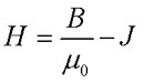
where B is the magnetic induction,
μ 0 - magnetic constant, μ 0 \u003d 4π * 10 -7 H / m.
At the same time, the magnetization vector J related to magnetic field strength IN a parameter that characterizes the magnetic properties of a substance and is called magnetic susceptibility χ
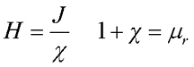
where J is the vector of magnetization of the substance,
However, the most often used to characterize the magnetic properties of substances is the relative magnetic permeability μ r.
Thus, the relationship between intensity and magnetic induction will be as follows
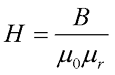
where μ 0 is the magnetic constant, μ 0 \u003d 4π * 10 -7 H / m,
μ r is the relative magnetic permeability of the substance.
Since the magnetization of the vacuum is zero (J \u003d 0), then the magnetic field strength in vacuum will be equal to
From here, you can derive the expressions for the intensity for the magnetic field created by a straight wire with current:
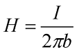
where I is the current flowing through the conductor,
b is the distance from the center of the wire to the point at which the magnetic field strength is considered.
As you can see from this expression, the unit of measurement of tension is ampere per meter ( A / m) or oersted ( E)
Thus, the magnetic induction IN and tension H are the main characteristics of the magnetic field, and the magnetic permeability μ r - the magnetic characteristic of the substance.
Magnetization of ferromagnets
Depending on the magnetic properties, that is, the ability to magnetize under the influence of an external magnetic field, all substances are divided into several classes. Which are characterized by different values \u200b\u200bof the relative magnetic permeability μ r and magnetic susceptibility χ. Most substances are diamagnets (χ \u003d -10 -8 ... -10 -7 and μ r< 1) и paramagnets (χ \u003d 10 -7 ... 10 -6 and μ r\u003e 1), somewhat less common ferromagnets (χ \u003d 10 3 ... 10 5 and μ r \u003e\u003e 1). In addition to these classes of magnets, there are several more classes of magnets: antiferromagnets, ferrimagnets and others, but their properties manifest themselves only under certain conditions.
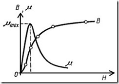
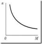
Ferromagnetic substances of special interest in radio electronics. The main difference between this class of substances is the nonlinear dependence of magnetization, in contrast to para- and diamagnets, which have a linear dependence of magnetization J from tension H magnetic field.
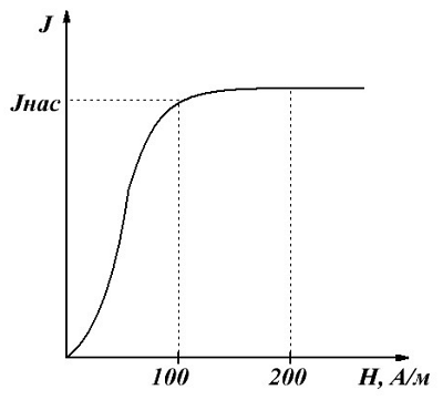
Dependence of magnetization J ferromagnet from tension H magnetic field.
This graph shows basic magnetization curve ferromagnet. Initially, the magnetization J, in the absence of a magnetic field (H \u003d 0), is zero. As the intensity increases, the magnetization of the ferromagnet is quite intense, due to the fact that its magnetic susceptibility and permeability are very high. However, upon reaching the magnetic field strength of the order of H ≈ 100 A / m, the increase in magnetization stops, since the saturation point J NAS is reached. This phenomenon is called magnetic saturation... In this mode, the magnetic permeability of ferromagnets drops sharply and with a further increase in the magnetic field strength tends to unity.
Ferromagnet hysteresis
Another feature of ferromagnets is the presence, which is a fundamental property of ferromagnets.
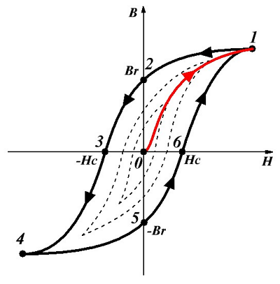
To understand the process of magnetization of a ferromagnet, we depict the dependence of the induction IN from tension H magnetic field, where we highlight in red basic magnetization curve... This dependence is rather uncertain, since it depends on the previous magnetization of the ferromagnet.
Take a sample of a ferromagnetic substance that has not been magnetized (point 0) and place it in a magnetic field, the strength H which we begin to increase, that is, the dependence will correspond to the curve 0 – 1 until magnetic saturation is reached (point 1). A further increase in the tension does not make sense, because the magnetization J practically does not increase, and the magnetic induction increases in proportion to the strength H... If you begin to reduce tension, then the dependence B (H) will fit the curve 1 – 2 – 3 , while when the magnetic field strength drops to zero (point 2), then the magnetic induction will not fall to zero, but will be equal to a certain value B rwhich is called residual induction, and magnetization will matter J rcalled residual magnetization.
To remove residual magnetism and reduce residual induction B r to zero, it is necessary to create a magnetic field opposite to the field that caused the magnetization, and the intensity of the demagnetizing field should be H withcalled coercive force.With a further increase in the strength of the magnetic field, which is opposite to the initial field, saturation of the ferromagnet occurs (point 4).
Thus, when an alternating magnetic field acts on a ferromagnet, the dependence of the induction on the strength will correspond to the curve 1 – 2 – 3 – 4 – 5 – 6 – 1 , which is called hysteresis loop... There can be many such loops for a ferromagnet (dashed curves), called private cycles. However, if saturation occurs at the maximum values \u200b\u200bof the magnetic field strength, then it turns out maximum hysteresis loop (solid curve).
Since the magnetic permeability μ r of ferromagnets has a rather complex dependence on the magnetic field strength, therefore, two parameters of the magnetic permeability are normalized:
μ n - the initial magnetic permeability corresponds to the strength H \u003d 0;
μ max - the maximum magnetic permeability is achieved in a magnetic field when magnetic saturation approaches.
Thus, in ferromagnets, the values \u200b\u200bof B r, H c and μ n (μ max) are the main characteristics that affect the choice of a substance in a particular case.
Theory is good, but theory without practice is just a shake of air.