Measurement of power and energy scheme. Measurement of power of constant and alternating single-phase current
From an expression for power on a constant current P \u003d IU, it can be seen that it can be measured using an ammeter and a voltmeter with an indirect method. However, in this case, it is necessary to produce a simultaneous counting on two instruments and calculations, complicating measurements and reduce its accuracy.
To measure power in chains of constant and apply appliances, called wattmeters for which electrodynamic and ferrodynamic measuring mechanisms are used.
Electrodynamic wattmeters are produced in the form of portable devices of high accuracy classes (0.1 - 0.5) and used for accurate measurements of the power of direct and alternating current at an industrial and increased frequency (up to 5000 Hz). Ferrodynamic wattmeters are more often found in the form of shield devices relative to the low class accuracy (1.5 - 2.5).
Apply such wattmeters mainly on alternating current industrial frequency. At constant current, they have a significant error due to hysteresis of cores.
To measure the power at high frequencies, thermoelectric and electronic wattmeters are used, which are a magnetoelectric measuring mechanism, equipped with an active power converter in a constant current. In the power converter, the Multiplication operation is carried out by Ui \u003d P and the receipt of the signal at the outlet depending on the product Ui, i.e. from power.
In fig. 1, but the possibility of using an electrodynamic measuring mechanism for building a wattmeter and power measurement is shown.
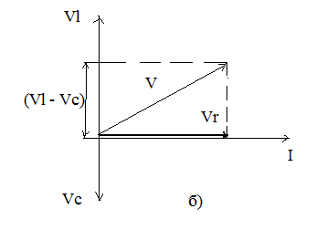
Fig. 1. Wattmeter inclusion scheme (a) and vector diagram (b)
Fixed coil 1, included in the load circuit consistently, called sequential chain Wattmeter, movable coil 2 (with an added resistor), included in parallel load - with a parallel chain.
For a wattmeter running on constant current:
![]()
Consider the operation of the electrodynamic wattmeter on alternating current. Vector diagram rice. 1, used for inductive load nature. The current vector of the currently parallel chain is lagging behind the U on the angle γ Due to some inductance of the movable coil.
From this expression it follows that the wattmeter measures the power correctly only in two cases: at γ \u003d 0 and γ \u003d φ.
Condition γ \u003d 0 can be achieved in a parallel chain, for example, the condenser with an appropriate container is shown, as shown by the dashed line in Fig. 1, a. However, the stress resonance will only be at a certain frequency. With the change in frequency, the condition γ \u003d 0 is broken. With γ not equal to 0 wattmeter measures the power with the error of β y.which carries the name of the corner error.
With a small corner value γ (Γ is usually no more than 40 - 50 "), relative error
At angles φ, close to 90 °, an angular error can reach large values.
The second, specific, error of wattmeters is the error due to the power consumption by its coils.
When measuring the power consumed by the load, two, characterized by the inclusion of its parallel chain (Fig. 2).
Fig. 2. Inclusion schemes parallel winding wattmeter
If you do not take into account phase shifts between currents and stresses in coils and consider the load H purely active, error β (a) and β (b), due to the power consumption of the wattmeter coils, for figures. 2, a and b:
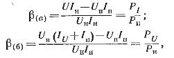
where R. i and RU - respectively, the power consumed by the sequential and parallel wattmeter chain.
From the formulas for β (A) and β (b) it can be seen that the errors may have noticeable values \u200b\u200bonly when measuring the power in low-power circuits, i.e. when Pi and Ru are commensurate with pH.
If you change the sign of only one of the currents, the direction of deviation of the movable part of the wattmeter will change.
Wattmeter has two pairs of clips (consistent and parallel chains), and depending on their inclusion in the circuit, the direction of deflection of the pointer may be different. To properly turn on the wattmeter, one of each pair of clamp is indicated by the "*" (asterisk) sign and is called the "generator clamp".
Ministry of Education and Science of the Russian Federation
Penza State University
Department "Metrology and Quality Systems"
Abstract on the topic
"Measurement of electric power and energy"
Performed: Art. c. 07Pts1
Okakova E. Kh.
Checked: to. T. N., Doc.
Safronova K. V.
Penza, 2009.
Introduction ................................................................................. ..3
1 Power Measurement in high and high frequency circuits ............... 6
2 Measurement of pulse power ................................................ .11
A) method of measuring medium power taking into account the coefficient
fill .............................................................................. ..1.1.
B) Power comparison method direct current……………………..12
C) integrally - differential method ................................. ... 13
D) method of sampling with memorization of samples ............................14
3 Digital power meters ................................................ ..15
4 AC power meters on
the basis of induction measuring mechanisms .............................. 16
5 Digital counters electrical Energy……………………………….18
List of references used ..................................................................20
Introduction
Power measurement is carried out in the circuits of direct and alternating currents of low, high frequency, as well as in pulsed circuits of various measuring, electrical, radio receiving and transmitting equipment. The range of the measured capacities lies in the range of 10 -16 - 10 9 W.
Measurement methods differ significantly from each other depending on the parameters of the circuit in which the power is measured, the change limit of the power and frequency range.
In the DC circuits, the load capacity of the load is determined by the current in the load and the voltage drops on it:
P \u003d ui \u003d i 2 R.
In alternating current circuits, the instantaneous value of the consumption power: p (t) \u003d u (t) i (t).
If u (t) and i (t) - periodic functions of time with a period t, then the average value of the power of consumption for the period is called power, or the active power of R. Power P with an instantaneous power value P (T) is related to the expression
P \u003d 1 / t ∫ p (t) dt \u003d 1 / t∫ uidt.
Power is measured in absolute units - watts, watt derivatives and relative units - decibelvatts ± α \u003d 10lg (P / P / PO), where P is an absolute value of power in watts (or millivatts), Po - zero (countable) power level equal to 1 MW ( or 1 MW) associated with absolute zero voltages UO and current IO through the standard resistance of the RO ratio Po \u003d U 2 O / RO \u003d i 2 O RO. For measuring power, direct and indirect measurement methods use. Direct measurements are carried out with the help of electrodynamic, ferrodynamic and electronic wattmeters, indirect - are reduced to the determination of power through an ammeter and a voltmeter or oscilloscope.
Reactive power must be minimized; Electricity providers are punished by consumers for inclusion in the network of loads with a poor power factor. Figure 1 shows a diagram operating on alternating current. It can be seen that the reactive power can be excluded if measures to ensure the equality of VC \u003d VL, that is, perform the correction of the power factor.
At low frequencies, power is usually calculated by measured current and voltage values. At high frequencies exceeding 1 MHz, more convenient and accurate power measurements, and voltage and current can be calculated. At frequencies above 1 GHz, the concepts of voltage and current lose meaning, and the power remains almost the only measurable parameter.
In the AC circuit, the power changes continuously with voltage and current changes. The devices measure the middle or constant power, which when working on radio frequencies means averaging for a large number of cycles. The period in which averaging is performed depends on the type of signal. For a continuous signal, power is averaged by a large number of high-frequency periods. In the case of an amplitude-modulated signal, the averaging of power is carried out in several cycles, and for a pulse signal - by a large number of pulses.
The relative results of power measurement are often expressed in decibels (dB). Decibel is one tenth bel. For example, if P2 is the power at the inlet of the amplifier, and P1 is the output power, then the gain coefficient is equal
G (dB) \u003d 10lg P1 / P2.
Decibel is convenient for power measurement because it provides a more compact record form; To find the strengthening of the multi-stage scheme, it suffices to fold the gain coefficients of individual cascades instead of multiplying them.
On network and low frequencies, an electrodynamic measuring mechanism is most widely used. It is suitable for measuring relatively high power levels.
The devices intended for measuring the power at high and ultra-high frequencies are two types: absorbing power meters containing their own load, and measuring lines in which the load is located at some distance. The absorbing devices are more accurate and typically include a 50-ohm load for working at high frequencies.
Measurement of power in circuits of increased and high frequencies.
In high and high frequency circuits, direct and indirect power measurements are carried out. In some cases, indirect measurements are preferable, as it is easier to measure the voltage, current and resistance than power. Direct measurements are mainly carried out using electronic wattmeters. In some electronic wattmeters, electrodynamic measuring mechanisms are used with a pre-amplification of current and voltage or with a preliminary straightening of these values. As a measuring mechanism, an electrostatic electromer with voltage and current amplifiers can be used, as well as magnetoelectric mechanisms with quadrators. Squares are performed on semiconductor diodes, transducers and other nonlinear elements, the operation of which is carried out on the quadratic area of \u200b\u200bthe Volt-ampere characteristic. The simulation operation of the UI in the quadrators is replaced by the operations of summing and construction in the square. In the frequency range to hundreds of megahertz, the wattmeters with the hall sensors are used.
At ultra-high frequencies, power is measured by power transformation into heat (calorimetric methods), light (photometric methods), etc.
Calorimeter. Calorimeters are used to measure high power mainly in metrological laboratories. The calorimeter consists of load resistance in the heat insulating body, immersed in a liquid or an air environment. The fluid may be fixed or flow into the calorimeter and flow from it at a certain speed. Fluid temperature at the output and input are measured. If R is the refrigerant flow rate in [cm 3 / s], D is its density in [g / cm 3], S - specific heat refrigerant, TI - its temperature at the entrance and that - at the output, then the power of PI, dissipated in the calorimeter, is determined by the expression
Pi \u003d (TO - TI) RDS / 0, 2389 W
In calorimetric measurements, we apply a substitution method. For example, after performing high-frequency measurements to the calorimeter, a DC power is supplied, giving the same temperature difference
(T - TI) under the same cooling conditions. Then the power of the DC is measured and is considered equal to the power of the high-frequency signal.
Power measurement by electronic rectifier wattmeter.The fundamental schemelelectronic wattmeter with a square, made on semiconductor diodes, is shown in Figure 2. The wattmeter has two resistors in the circuit of the current, the resistance of which R1 \u003d R2 is much less than the load resistance, and two resistors resist R3, R4 in the voltage circuit. Resistors R3 and R4 perform the role of a voltage divider, so the resistance R3 + R4 is a lot more resistance Load ZH.
The voltage drop on the resistors R1 \u003d R2 is proportional to the load current of the K1i, the voltage drop on the r3 resistor of the divider is proportional to the voltage at the load, that is, the K2U. As can be seen from the circuit, voltage U1 and U2 on VD1 and VD2 diodes will be, respectively:
u1 \u003d k2u + k1i; U2 \u003d K2U - K1i.
In identical characteristics of the diode and work on the quadratic section of the Volt-ampere characteristics of currents I1 and I2 are proportional to the squares of the voltage.
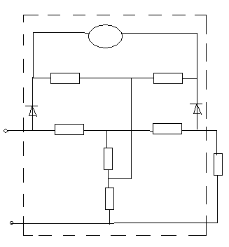
Figure 2. Schematic scheme Electronic rectifier wattmeter
Current in the chain of the device II \u003d (I1 - I2) R / RG. The constant current component measured by a magnetoelectric device at u \u003d umaxsinωt and i \u003d imax sin (ωt ± φ) is proportional to the active power:
I \u003d 1 / t∫kuidt \u003d k 1 / t uidt \u003d kuicosφ \u003d kpx,
where PX is the measured power.
Electronic wattmeters, in the scheme of which diodes are included, have low accuracy, measurement error ± (1.5 - 6)%, low sensitivity, high power consumption, limited frequency range.
Measuring power thermoelectric wattmeter.The frequency range can be extended to 1 MHz if the square is built on contactless thermal converters. The thermoelectric wattmeter differs from rectifying the fact that instead of diodes, the heaters of the contactless thermocouple turn on, and the thermo-emf difference at the cold ends, measured by a magnetoelectric malelololtmeter, is proportional to the average load capacity of the load.
Thermogottmeters are used when measuring the power in circuits with a non-sinusoidal form of current and voltage; When measuring power in chains with a large phase shift between voltage and current, when determining the frequency error of electrodynamic wattmeters.
Measuring the power of the wattmeter with the hall converter. The Hall converter is a four-pole, made in the form of a thin semiconductor monocrystalline plate. Current conclusions T - T The Hall Converter connects to an external source of direct or alternating current, potential leads
X - X, between which the EMF occurs at the time when the magnetic field affects the plate - to the voltage meter. The conclusions of x - are joined by side faces in the equipotential points in the absence of an external magnetic field.
Hall powerful power
where kx is a coefficient whose value depends on the material, sizes and shape of the plates, as well as on temperature ambient and meanings magnetic field; B is magnetic induction.
The electromotive power of the Hall will be proportional to the power, if one of the output values \u200b\u200bto make the proportional voltage u, and the other - current through the load.
To implement, the Hall converter is placed in the clearance of the electromagnet, the magnetizing coil of L which is powered by a current proportional to the load current, and through T - T passes the current, proportional to the voltage applied to the load z. The current value is limited to the additional resistor RD. EMF Hall EX \u003d KUI \u003d KP is registered with a magnetoelectric milvololtmeter (k - proportionality coefficient). Measures electric power and energy. Such devices were developed ... and sensitive digital means measurements electric power and energy. Widespread use of measuring ...
Measure electric Resistance Single DC Bridge
Laboratory work \u003e\u003e Industry, productionResistance. Introduction For measurements electric Resistance The following methods are applied ... with significant currents powerallocated on the resistances ... literature 1.Popov V.S. Electrotechnical measurements. M.: Energy. 1974. GL.6. 2.Savely ...
Three-phase electric chains electric cars, measurements electric energy, electric Lighting, straightening alternating current
Tutorial \u003e\u003e Physics... electric chains electric machines, measurements electric energy, electric Lighting ... Electric energy equal to the work power electric Chains for a while: where r - power, W; T - Time, p. Unit measurements electric energy ...
Power and coefficient power in alternating current circuits
Laboratory work \u003e\u003e Physics... eNERGY current to thermal and (or) mechanical eNERGYreactive electric power current is converted to the appropriate reactive load in eNERGY ... Results measurements. 1. Consider full power P, coefficient power COS and reactive power ...
From the expression for power on a constant current, it can be seen that it can be measured with an ammeter and voltmeter with an indirect method. However, in this case, it is necessary to produce a simultaneous counting on two instruments and calculations, complicating measurements and reduce its accuracy.
To measure the power in circuits of constant and single-phase alternating current, appliances are used, called wattmeters for which electrodynamic and ferrodynamic measuring mechanisms are used.
Electrodynamic wattmeters are produced in the form of portable devices of high accuracy classes (0.1 - 0.5) and used for accurate measurements of the power of direct and alternating current at an industrial and increased frequency (up to 5000 Hz). Ferrodynamic wattmeters are most often found in the form of shield devices relative to low accuracy class (1.5 - 2.5).
Apply such wattmeters mainly on the alternating current of industrial frequency. At constant current, they have a significant error due to hysteresis of cores.
To measure the power at high frequencies, thermoelectric and electronic wattmeters are used, which are a magnetoelectric measuring mechanism, equipped with an active power converter in a constant current. In the power converter, the multiplication operation and the receipt of the signal at the outlet, depending on the product Ui, i.e. from the power.
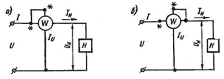
Fig. 8.3.
If you do not take into account phase shifts between currents and stresses in coils and consider the load h of purely active, error and caused by the power consumption of the coils of the wattmeter, for schemes (Fig. 8.3):


where and - accordingly, the power consumed by the sequential and parallel wattmeter chain.
From the formulas for and it can be seen that the errors may have noticeable values \u200b\u200bonly when measuring the power in low-power circuits, i.e., when and commensurate with.
If you change the sign of only one of the currents, the direction of deviation of the movable part of the wattmeter will change.
The wattmeter has two pairs of clamps (serial and parallel chains), and depending on their inclusion in the circuit, the direction of the rejection of the pointer may be different. To properly turn on the wattmeter, one of each pair of clamp is indicated by the sign "*" (asterisk) and is called "generator clamp".
Measuring Power Using Hall Effect
Multiplier of the values \u200b\u200bof the strength of the current and the potential difference when measuring the power can be obtained using the Hall semiconductor transducers.
If a special semiconductor plate at which current I flows (Fig. 8.4), excited electric field tension E, put in a magnetic field with H (induction B), then between its points lying on the direct, perpendicular directions of the flowing current I and the magnetic field, the potential difference occurs (Hall Effect), defined as
![]()
where k is the proportionality coefficient.
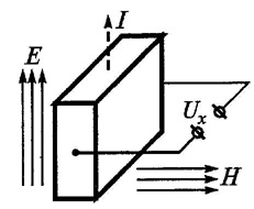
Fig. 8.4.
According to the Umova-Pointing theorem, the flow density of the undergoing power of microwave oscillations at some point of the field is determined by the vector product of the electrical and magnetic tensions of this field:
![]()
Hence, if the current i is a function electrical tension E, with the help of the Hall sensor, you can get the following voltage dependence on the passing power:
where G is a permanent coefficient characterizing the sample. To measure this power, the semiconductor plate (plate Hall - PC) is placed in a waveguide, as shown (Fig. 8.5).
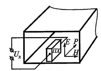
Fig. 8.5.
The considered power meter has the following advantages:
- can work with any load, and not only with consistent;
- the high speed of the wattmeter makes it possible to apply it when measuring pulsed power.
However, the practical implementation of wattmeters on the Hall effect is a rather difficult task due to many factors. Nevertheless, there are wattmeters that measure passing pulsed power up to 100 kW with an error of no more than 10%.
Methods for measuring power at high and ultrahigh frequencies
Power in general is there physical quantitywhich is determined by the work produced per unit of time. Power unit - Watt (W) - corresponds to the power at which one second is performed in one JOUL (J).
On constant current and alternating current low frequency, the direct measurement of power is often replaced by measuring the active value. electric voltage On the load U, the active value of the current flowing through the load I, and the phase shift angle between the current and voltage. In this case, power is determined by the expression:
![]()
In the microwave range, the voltage and current measurement becomes difficult. The commensity of the size of the input circuits of measuring devices with a wavelength is one of the reasons for the ambiguity of the voltage and current measurement.
Measurements are accompanied by significant frequency errors. It should be added that the measurement of the voltage and current in the waveguide paths in some types of waves loses its practical meaning, since the longitudinal component is absent in the conductor, and the potential difference between the ends of any diameter of the waveguide cross section is zero. Therefore, at frequencies, starting with dozens of megahertz, the direct measurement of power becomes preferable and more accurate, and at frequencies above 1000 MHz is the only type of measurement, uniquely characterizing the intensity electromagnetic oscillations.
For direct measurement The microwave power is used methods based on fundamental physical laws, including the method of direct measurement of the main values: mass, length and time.
Despite the variety of methods for measuring microwave power, all of them are reduced to the transformation of the energy of electromagnetic microwave oscillations into another type of energy available for measurement: thermal, mechanical, etc. Among the devices for measuring microwave power, wattmeters based on thermal methods were most common. A number of other methods are also used - ponderomotor, probe and others.
The principle of the overwhelming majority of microwave power meters, called wattmeters, is based on measuring changes in temperature or resistance of elements in which the energy of the studied electromagnetic oscillations is scattered. The instruments based on this phenomenon include calorimetric and thermistor power meters. Wattmeters were obtained using ponderomotor phenomena (electromechanical forces), and wattmeters operating on the Hall effect. The peculiarity of the first of them is the possibility of absolute power measurements, and the second - measurement of power, regardless of the coordination of the RF path.
According to the method of inclusion in the transmitting path, the wattmeters of the passing type and absorbing type are distinguished. The wattmeter of the passing type is a four-pole, in which only a small part of the total capacity is absorbed. The absorbing type wattmeter, which is a two-pole, connects at the end of the transmitting line, and, in the ideal case, the entire power of the incident wave is absorbed in it. The wattmeter of the passing type is often performed on the basis of the absorbing type meter included in the tract through the directional branch.
Calorimetric methods for measuring power are based on the transformation of electromagnetic energy into heat in the load resistance, which is part of meter. The amount of heat released is determined according to the temperature change in the load in the load or in the medium where heat is transmitted. There are static calorimeters (adiabatic) and streaming (non -adiabatic). In the first, the microwave power is dissipated in thermally insulated load, and the continuous flow of calorimetric fluid is provided. Calorimetric meters allow measurement of power from units of millivatt to hundreds of kilowatt. Static calorimeters measure small and medium power levels, and the stream - medium and large values Power
The heat balance condition in the calorimetric load is:
![]()
where P is the microwave power dissipated in the load; T and t 0 - load temperature and environment, respectively; C, M is the specific heat capacity and the mass of the calorimetric body; K - thermal scattering coefficient. The solution of the equation seems to be
![]()
where is the thermal time constant.
In the case of a static calorimeter, the measurement time is much less permanent and microwave power is:
![]()
The main elements of static calorimeters are thermally insulated load and a temperature measurement device. It is easy to calculate the absorbed power of the microwave for the measured rate of increasing temperature and the known heat capacity of the load.
In additions, various high-frequency terminals made of solid or liquid dielectric material with losses are used, as well as in the form of a plate or high resistance film. To determine the temperature change, thermocouples and various thermometers are used.
Consider a static calorimeter, which reduces the requirements for thermal insulation and there is no need to determine the heat capacity of the calorimetric nozzle (Fig. 8.6). This scheme uses substitution method. In it, in order to calibrate the device 4, measuring the temperature rise in the scattering of the measured power supplying to the shoulder 1, the known power of the DC or the low frequency current is used, supplied to the shoulder 2. It is assumed that the nozzle temperature 3 changes the same when scattering equal power values \u200b\u200bof the microwave and direct current. Static calorimeters allow you to measure the power of several millivatts with the error of less.