Reed switch normally closed marking. Reed switch (sealed contact), normally open. The principle of operation of the reed switch
These sensors were purchased on a tip from the comments to one of my past reviews.
By and large, there is nothing to review here, since the principle of their operation is simple, but one of my comrades became interested in what it is and how it works - I decided to write this small visual review about this.
Principle of operation
Compared with other relay technologies, reed relays have the advantages of hermetically sealed contacts, low coil power, fast operation and small size. However, as with any technology, there are various aspects to consider.
Reed relays are usually mounted on printed circuit boards. Reed terminals must not be bent, for example, in order to self-lock. Avoid bending the terminals to fit the offset holes. Unshielded relays placed too close together can influence each other. Shielded relays are an option in this case and for environments with high magnetic fields from motors, magnets, etc.
reed switch ( ger crossbred con tact) is a glass cone, inside of which there are two elastic contact ferromagnetic plates, which, when immersed in a magnetic field, close and a contact is formed, through which current then flows.
The cone is usually filled with an inert gas or contains a vacuum. An example of work is schematically shown in the animation below, where an ordinary magnet is brought up.
Today, Hall effect technology allows the creation of complex sensors used in a wide range of automotive, electronic and industrial products. The Hall effect device is an integrated circuit based on semiconductors with Hall plates that respond to magnetic fields. Unlike a reed switch, a Hall effect device contains active circuitry, so it draws a small amount of current at any one time. Hall effect devices are available in two- or three-wire versions.
Temperature, voltage and power
Some devices are programmable. Like all solid state semiconductor devices, Hall sensors have a maximum operating junction temperature. The hot junction temperature is determined by the power dissipated by the sensor, the thermal resistance of the package, any heat dissipation effects resulting from mounting, any air movement and temperature. environment. Due to internal power dissipation and self-heating, the maximum working temperature may need to be reduced if more high voltages supply to limit the junction temperature to an acceptable value.
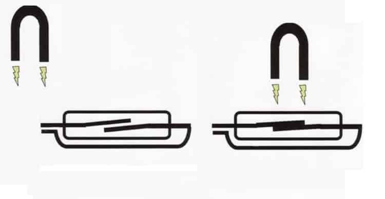
Why do the plates actually close and open from the presence of magnetic field. As mentioned above, the plates themselves are ferromagnetic, i.e. they actively attract the magnet to themselves and at the same time they themselves are actively attracted by the magnet. Similar properties are found in ordinary iron. The magnet has two polarities - north and south, and the magnetic lines always go from the north pole to the south. When bringing the magnet to the reed switch, the magnetic lines will also pass through these elastic plates. In this case, in the figure, the north pole of the magnet is located on the left, the south - on the right. Accordingly, the edge of the upper plate becomes the south polarity, and the edge of the bottom plate becomes the north polarity - as a result, the plates close. When the magnet moves away, the plates open due to their elasticity. If the magnet is not positioned correctly in relation to these plates, then the magnetic lines will pass through them unevenly, and the contacts will not be able to close. 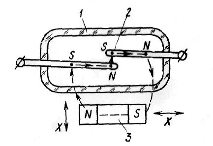
Semiconductor products are sensitive to ESD events. Consists of two very small ferromagnetic blades or "reeds" inserted into either end of a tiny glass tube. The glass tube is hermetically sealed during production.
Ferromagnetic blades placed in a magnetic field are induced to move towards each other until the contacts close at both "free" ends in the central part of the tube. This closes the previously interrupted circuit and enables the toggle function. Once the magnetic field is removed, the solid blades will shut off again, breaking the circuit again.
Three main types of reed sensors can be found on sale:
1)
Normally open (observable), which are normally open, and when immersed in a magnetic field, the circuit closes.
2)
Normally closed - already the opposite principle: in the normal state, the contacts are closed, but when immersed in a magnetic field, the contacts open.
3)
Reed switches, unlike the first two, already have 3 outputs and 3 plates inside, respectively. In a calm state, one pair of contacts is closed; when immersed in a magnetic field, another pair is already closed.
There are two main types of reed switches: a switch type with two ferromagnetic blades that are normally open in the absence of a magnetic field, as described above, and one with three blades. In the latter, one paddle is inserted at one end and two paddles at the other end into the tube. This creates two contact surfaces in the middle. In the absence of a magnetic field, a single blade contacts a "normally closed" contact, but as soon as the field appears, the position changes to a "normally open" contact.
According to the manufacturing technology and design, reed switches are divided into groups
A microscopic layer of precious metal is applied to the reed contacts to ensure optimum electrical contact. The preferred metal for this is low resistance silver. However, some reed switches use mercury. Because the contacts are "wetted" with mercury, the switches must be held in specific directions during assembly to prevent liquid metal from entering and making the contacts rest.
Reed switches are also designed for switching high current or mercury, where the contact points of the plates are moistened with a drop of mercury to suppress contact bounce. The main application of reed switches is security and automation systems, as the simplest example - automatic start any action when a door or window is opened, such as sending an alarm. On the basis of reed switches, reed relays are made - in high-voltage installations, these are used to protect against overcurrent, in this case the reed switch is placed in a coil.
By the year, the demand for reed switches was steadily increasing. Even today they are still used in many various devices communications, as well as proximity sensors on door and window alarm systems, to name just two of many different applications.
What it is?
Because the international demand for reed switches is so great, they must be mass produced. However, they require precise and reliable sophisticated microfabrication. This requires an extremely clean environment that does not even contain microscopic dirt particles. Otherwise, contaminants will settle in the hermetically sealed glass tubes and interfere with the operation of the switch.
Appearance. Dimensions
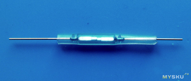
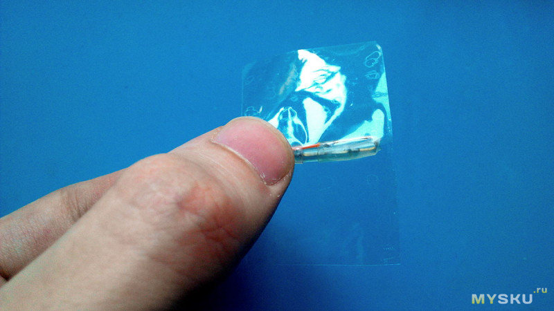
I took normally open (open) in the amount of 10 pieces.
Glass capsule with a slightly greenish tint. 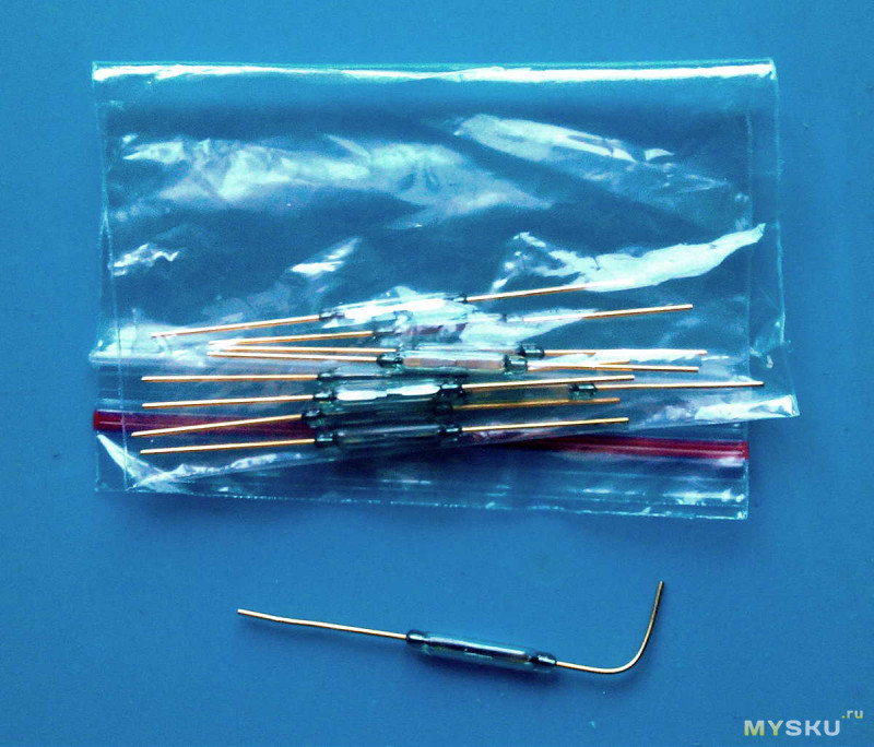
Dimensions correspond to 2x14mm 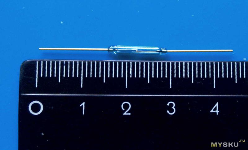

The contacts of the ferromagnetic reeds consist of a nickel-iron alloy with a nickel content of 52%. A microscopically thin layer of iridium, rhodium or ruthenium is applied to the contacts. The bottom layer is made of tungsten, copper or gold. The glass tube, whose coefficient of thermal expansion corresponds to the thermal expansion of nickel-iron alloy, is tightly closed around the reed at each end by heating infrared radiation in the form of lasers until the hole is closed. During the sealing process, the glass cavity is filled with an inert gas such as nitrogen.
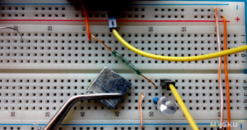
Assembled on a breadboard simple chain with an LED, in the gap of which the reed switch was placed in order to check its operation by bringing a flat neodymium magnet to it, and since the magnetic fields have different poles, the contacts in the reed switch are stably closed only if the magnet is directed at it end face and across. 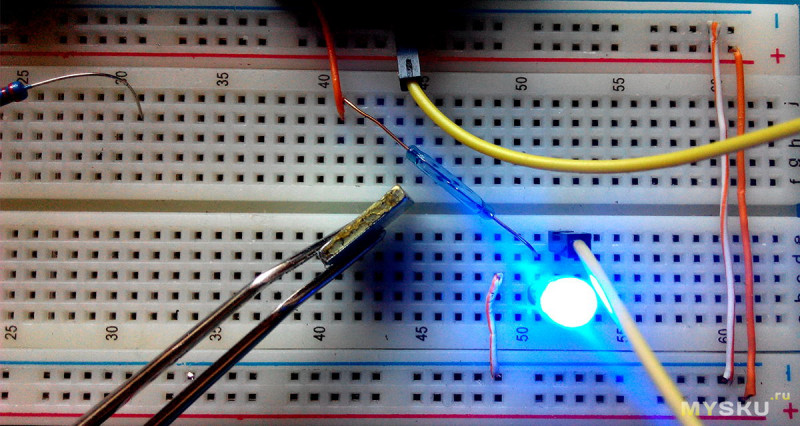
Fields of application of microswitches in production. Reed switches are still widely used for control power circuits in the communications industry, but are also widely used as proximity sensors in alarm systems, usually mounted on windows or doors.
They also allow laptops to sleep when the lid is closed, and are used in computer keyboards: each contact has a built-in magnet that activates the switch as soon as a key is pressed. Meanwhile, the latter use has largely given way to less costly alternatives.
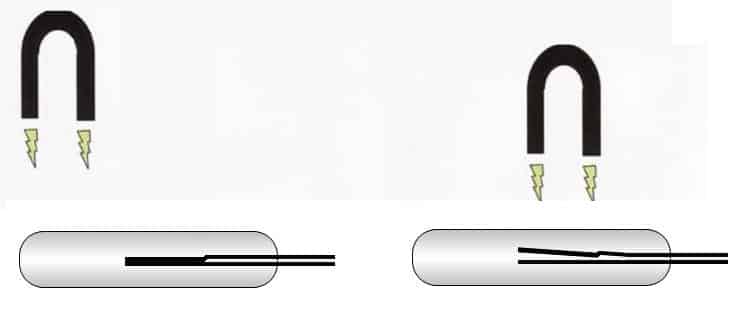
In other positions of the magnet, the contacts in the reed switch will not be closed: 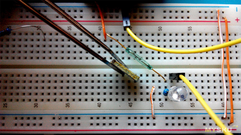
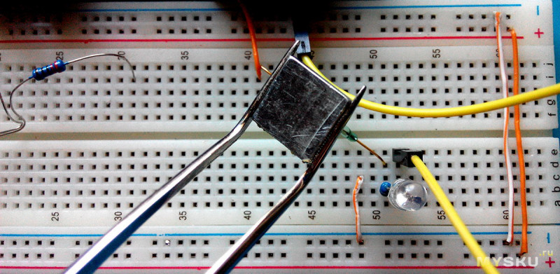
An example with magnets from a motor: turning one side - the contacts close, the other side - no reaction. Therefore, this point should be taken into account.
In cars and bicycles, magnets attached to the tires activate the reed switches each time they pass the switch sensor, allowing them to act as accurate speed sensors. Even devices used in high pressure environments such as diving cameras and flashlights are usually equipped with reed switches so a waterproof seal is given.
Differences between reed switches and other switches. Unlike other electrical switches, reed switches are specifically designed to be sensitive to the presence and absence of magnetic fields. Because of this property, these switches are used in various applications.
How the state of the plates changes - in an enlarged view under a digital microscope
In addition to everything, it would be nice to show the simplest visual test of the operation of this sensor with the performance of some action when opening and closing the door of the room, for example, turning on table lamp through .
First you need to pack the reed switch itself. 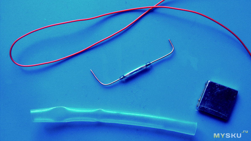
After melting, the contact tongues overlap inside the glass body and form an "air gap" in the contact zone. When approaching a sufficiently strong magnetic field, both contact tongues take on the opposite magnetic polarity and thereby close the contact.
- How does the reed switch work?
- Both tongues are covered with contact material in the contact area.
Basically, one differentiates. In addition, many reed switches are designed for special applications, e.g. High voltage insert, ultra miniature types for implants, etc. By applying voltage to the coil, current flows and a magnetic field is created. If you increase the current until you press the reed switch, you will get the attraction value. The amount of waste is determined by reducing the current until the switch drops.
A piece of heat shrink is put on, crimped with hot air 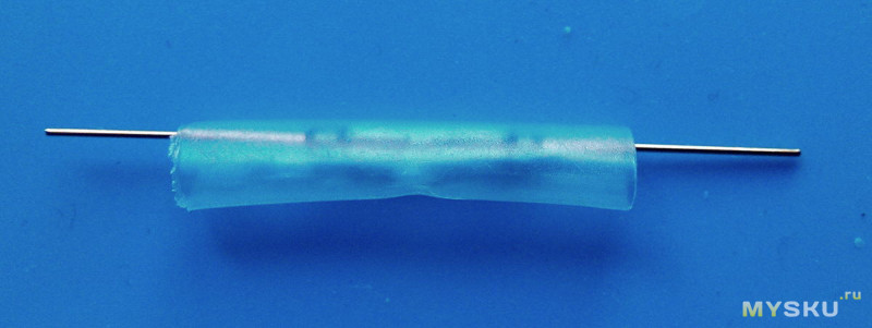
It is necessary to bend one conclusion. But then the first pancake was waiting for me with a lump - bending the output almost at the very base of the cone - the glass broke and the reed switch became unusable: ![]()
For example, the reed switch switches to a distance of 10 mm when approaching the magnet. However, the reed switch only trips when the magnet is 12mm away. There are special reed switches with very tight hysteresis. What is the life of reed switches?
With simple signal transmission, several 100 million switching cycles. The life of a reed switch is usually much longer than the life of the device in which it is used. In general, the same contact protection measures as for normal switch contacts should be observed so as not to reduce the life of the reed switch.
To prevent this from happening, you need a conclusion, stepping back from the base of the capsule by 1-2 mm, clamp it with tweezers and only then bend it: 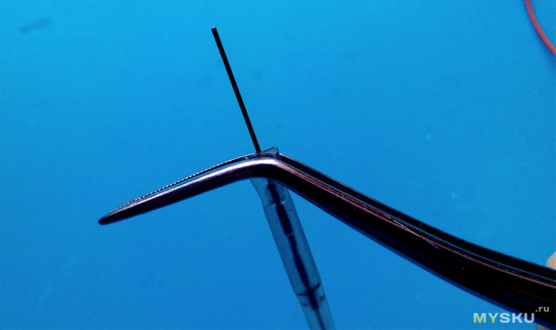
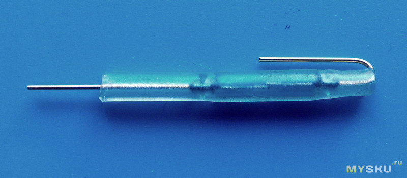
The second conclusion was slightly shortened, along with heat shrink 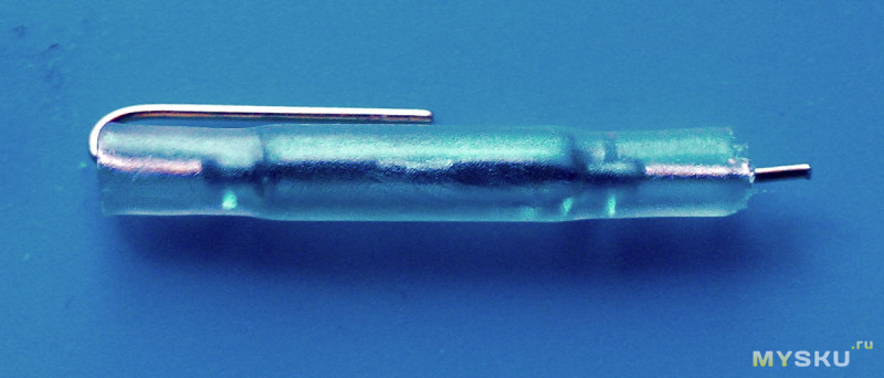
How to achieve the maximum distance between the reed switch and the magnet? How to achieve the highest possible switching accuracy? The ideal is a sharply delineated "point" magnetic field, which acts directly near the contact overlap zone, if we assume a single-pole control. The difference between switching distance between on and off is particularly low here.
- In addition, the reed switch must have the smallest possible hysteresis.
- The closer the magnet and reed switch are chosen, the better.
I solder the wire to both terminals of the wire 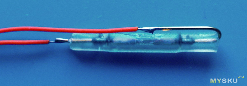
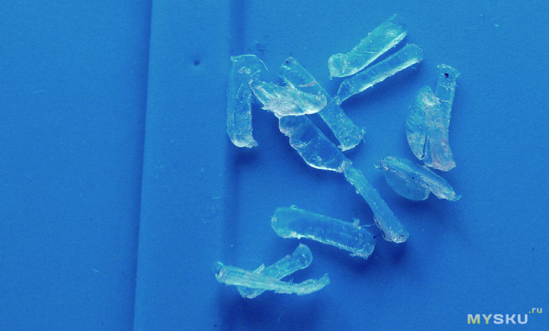
Now the whole thing needs to be fixed somehow. Therefore, I chopped the rod from the glue gun into small slices: 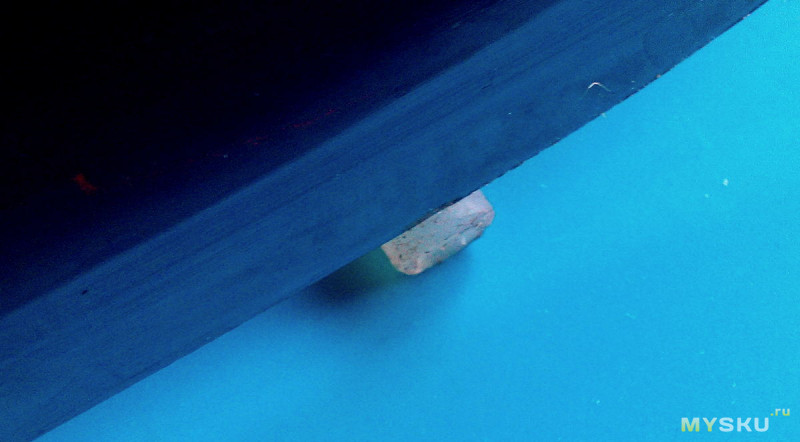
What is a reed sensor?
Only when the contacts lie on top of each other with sufficient contact pressure and maximum contact area can a continuous current flow. Therefore, the specified switching current is usually less than the DC current. What is the solderability of reed switches?
Reed switches can be soldered in all common ways. Do you supply axle belts? Are your products lead free or. More detailed information on this topic can be found in the section "Ecology". Right choice The material for the body is critical to the durability of the product. The chosen material should permanently protect the components inside the sensor.
I put more heat shrinks on top of the reed switch, at the base I stuffed a little hot glue scraps inside: 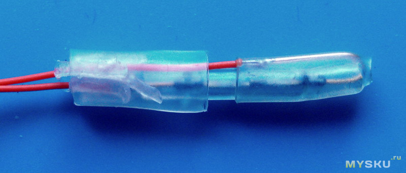
Blowed hot air 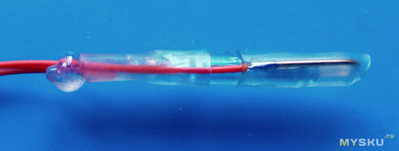
Removed excess glue 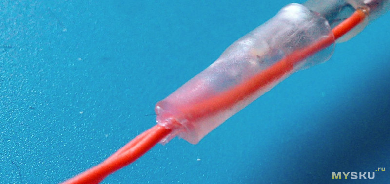
In the medium in which the sensor is used, the maximum pressure in the mechanical stress of the medium. Minimum and maximum ambient temperature. . We are happy to help you choose the right material for your application. The cane technology allows contactless switching of an electrical signal or voltage. In this case, a certain external magnetic field acts on a special contact of a ferromagnetic switch, also called reed switch. This magnetic field is usually generated by a permanent magnet or coil.
The matter is small. Attach the magnet to the door, and the reed switch to the wall, opposite the magnet. For an indicative test, ordinary scotch tape also fit here, since you can quickly remove everything back and forth. 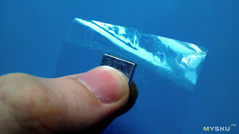
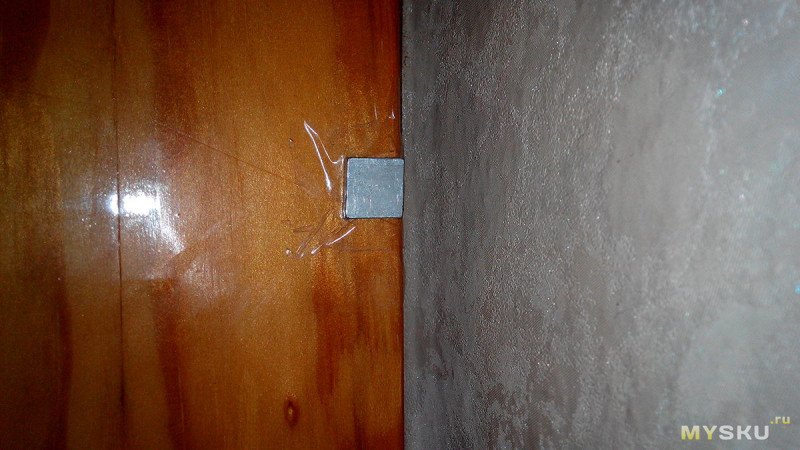
Non-contact, low wear resistance Long service life High switching frequency Cost effective alternative to electronic switches. Tripping Distance The tripping distance is the distance that the magnetic switch trips when approaching the magnet. The length of the switching distance depends on the strength of the magnet field and the sensitivity of the reed contact. Switching hysteresis The switching hysteresis is the difference between the switch-on and switch-off points. It depends mainly on the type of reed switch.
Switch point accuracy Magnetic switches have a very high switching point repeatability. For Hall element switches up to 100 kHz, depending on version. Switching capacity - example Max. The switching capacity is the product of the switching current and the switching voltage. However, the individual limit values must not be exceeded.
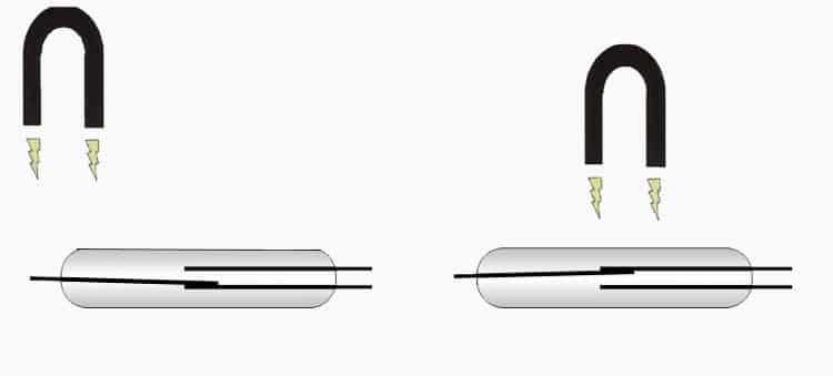
Magnet and reed switch are located across each other 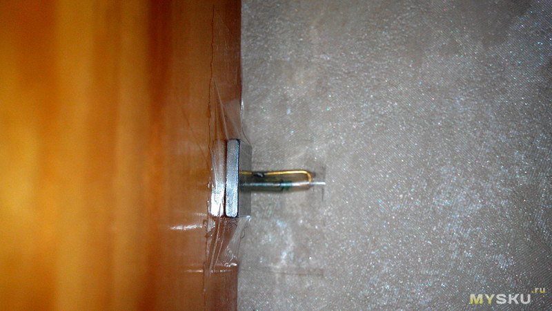
The electronic-software part is simple: the Pro Mini board is set to an external interrupt, where the interrupt output is connected to the power supply of the board through this same reed switch, and while the door is closed and there is a magnet near the reed switch, the circuit is closed, the controller is asleep, and the relays that control the lamp are off. As soon as the door opens and the magnet is moved aside, the reed switch opens, an external interrupt occurs, which gives a pulse to the relay and the lamp turns on.
There can be many applications in homemade products, especially with simple and cheap Attiny13 controllers or, if the project is very simple, with transistors. Due to its small size, the reed switch can be cleverly hidden from prying eyes. I will use them in new version energy-efficient GSM-alarm system, though for its full assembly it is necessary to wait for a few more components. Of the minuses, I note the fragility of the capsule and vulnerability to other magnetic fields. With regards to reliability, they write that they have a rather large closing-opening cycle due to the tightness inside the capsule. In general, we'll see.
I plan to buy +46 Add to favorites Liked the review +78 +137Any mechanical contacts are subject to wear. To reduce the influence of this destructive factor, in the first half of the last century, magnetically controlled switching devices were developed, the contact group of which was placed in a vacuum flask. In the USSR, such elements were called "Reed switch", short for "sealed contact", in the English-language technical documentation the name "reed switch" is adopted.
Let's look at the principle of operation of these devices, design, main characteristics, advantages and disadvantages. At the end of the article, a couple of useful schemes will be given where reed switches are used.
These devices are a contact group made on the basis of a ferrimagnetic material, which is placed in a glass flask. Air is pumped out of it (conditions are created as close as possible to vacuum), as an option, filling with an inert gas is possible. Appearance of the device and its designation on circuit diagrams are presented below.
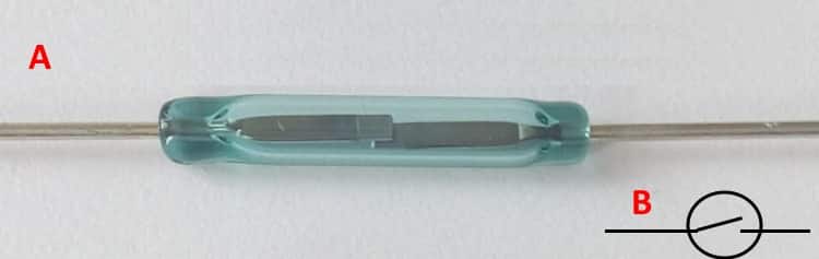
The design can be seen in Figure 2.
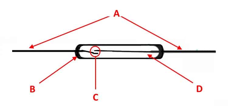
Designation:
- A - device outputs.
- B is a glass flask.
- C - contact group.
- D - inert gas or vacuum.
Varieties
Switching devices of this class are usually divided, depending on the device of the contact group, into the following types:
- Elements with normally open contacts ( appearance such a device is shown in Fig. one).
- Elements with normally closed contact.
- With changeover contact.
In addition to the functional features listed above, there are also technological ones that divide hermetic switching devices into two groups: dry and mercury. Distinctive feature The latter is that inside the flask contains a drop of mercury. It serves to "wet" the contact group, this can significantly reduce contact resistance and vibration (bounce) of contacts during switching, which positively affects the quality of the contact.
Operating principle
The operation of the device (closing, opening or switching contacts) is required to act on the element with a magnetic field, the intensity of which will be sufficient for switching. The source of such a field can be a conventional or electromagnet.
Under influence lines of force the contacts are magnetized and, upon overcoming the elasticity threshold, they commute the circuit.
Accordingly, as soon as the magnetic field ceases to act on the contact group, it will return to its original state. That is, functionally, the contacts, in addition to their direct purpose, play the role of a magnetic circuit and an elastic element.
Devices with normally closed contacts act somewhat differently. Their ferrimagnetic elastic elements, falling under the influence of a magnetic field, acquire the same charge, which causes them to repel, breaking the contact.
Sometimes in such switches only one elastic element is made of a ferrimagnetic alloy, as a result of the approach of a magnet, it is attracted to it, turning off the circuit.
A similar principle is used in reed switches with a switching group of contacts, in which two of them are made of magnetic material. Under the influence of a magnet, they are attracted to each other, and the non-magnetic contact remains in its original position. As a result, the circuit is switched.
main parameters
The properties of sealed switches are determined by mechanical and electrical parameters. The first ones include:
- N max - a number indicating the maximum allowable number of operations without changing the main characteristics.
- V cp - value reflecting the intensity of the field required for the response of the device. In technical terminology, this characteristic is called the magnetomotive force.
- V otp - the value corresponding to the opening force.
- t cp - the time required for the operation of the contact group.
- t otp - the time interval required for release.
- The last two parameters are the most significant of mechanical characteristics, since they describe the switching speed.
- Now we list the main electrical characteristics:
- R K - resistance between contacts in the closed state.
- R FROM - resistance of open contacts.
- U PR - breakdown voltage, this characteristic depends both on the previous parameter and the distance between the group of contacts. In addition, the dielectric strength is affected by the filling of the flask.
- P max - switched power.
- C K is the capacitance formed by open contacts.
How is management carried out?
The sealed switch can be controlled in two ways:
- using a permanent magnet;
- acting on a coil connected to a constant current source.
In the first variant, the control can be carried out by linear or angular movement of the permanent magnet. There is also a method in which the field is blocked using a special curtain.
As an example of the use of the magnetic control method, one can cite level sensors, as well as position sensors, burglar alarms, etc.
The second option allows you to create a relay based on a reed switch. Unlike the traditional design, such a device will be more reliable and durable, since it practically does not contain moving mechanical elements. As for the small number of contact groups, this disadvantage is easily eliminated by increasing the number of reed switches involved.
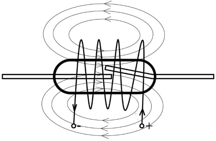
An example of the application of this control method is a current relay based on a reed switch. It is a coil wound with a thick wire, inside which a sealed switch is placed. This device can serve as a protective system against overload in circuits direct current. The sensitivity of the device can be easily adjusted by linear movement of the switch inside the coil.
Pros and cons
Any design, in addition to advantages, is not without disadvantages. Knowing the strengths and weak sides device, you can find the optimal scope for its application. Let's look at what the advantages of sealed switches are, these properties include:
- High switching reliability. It is almost two orders of magnitude higher than that of open contact groups. This is achieved due to the high resistance between open contacts (R FROM), it can be calculated in tens of MΩ. An important role is played by the indicator of electrical strength (U PR), the breakdown voltage for some models exceeds 10 kV.
- Speed is also an undeniable advantage. The switching frequency of many models approaches 1 kHz. As for the parameters describing the switching speed, they are in the following ranges: t cp - from 0.4 to 1.8 ms, t otp - from 0.25 to 0.9 ms, which is much higher than similar characteristics of open contact groups.
- Durability, the number of operations is in the billions, not a single open contact group can even come close to this milestone.
- This type of switches is undemanding to match with the load.
- The control can be carried out without the use of electricity.
Characteristic disadvantages:
- Low switching power.
- Small number of contacts.
- Chatter when triggered (wet-type designs are free from this drawback).
- Large dimensions for a modern radio engineering base.
- Insufficient strength of the glass flask.
- Sensitivity to external magnetic fields.
Despite the clear predominance of positive qualities, these devices are gradually being replaced by semiconductor counterparts, such as Hall sensors. The absence of chatter, small dimensions and higher strength played a decisive role.
Examples of practical application in everyday life
As promised at the beginning of the article, here are a couple of useful schemes that use reed switches. Let's start with universal lighting control in the hallway. The principle of operation is as follows: when you open the front door, the light automatically turns on, and after a few minutes it turns off. With a sufficient level of lighting, the light in the hallway does not turn on.
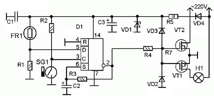
Designations:
- Resistors: R1 - 68 kOhm, R2 - 33 kOhm, R3 - 470 kOhm, R4 - 10 kOhm, R5 - 27 kOhm.
- Capacitors: C1 - 0.1 uF, C2 - 100 uF x 25 V, C3 - 470 uF x 25 V.
- Zener diode and diodes: VD1 - KS212Zh, VD2 and VD3 - KD522 (1N4148), VD4 - KD209 (1N4004).
- Transistors: VT1 and VT2 - ÌRF840.
- SG1 - any conventional reed switch, for example, 59145-030.
- FR1 - photoresistor, suitable for any type with resistance in the light of at least 8 kOhm, in the dark - 120-180 kOhm.
- Trigger D1 - K561TM2 (CD4013).
Setting up the circuit is reduced to the selection of resistance R1, to select the optimal delay time for turning off the lighting.
Now let's look at a simple home alarm circuit, where a typical reed sensor for a door is also used.
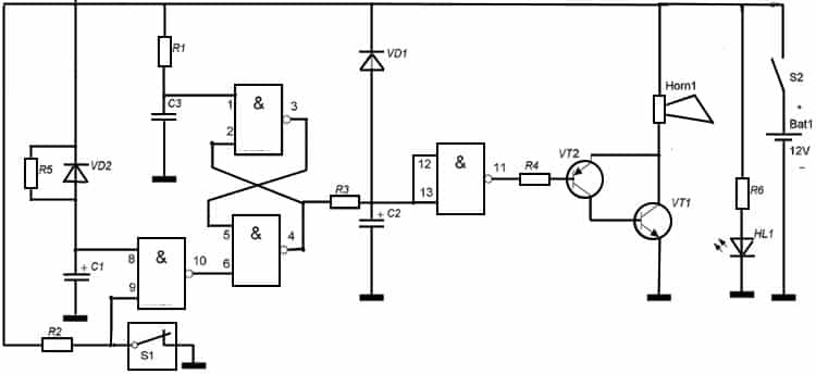
Designations:
- Resistors: R1, R2 and R3 - 100 kOhm, R4 - 33 kOhm, R5 - 100 kOhm, R6 - 1 kOhm.
- Capacitors: C1 - 100 uF x 16 V, C2 - 50 uF x 16 V, C3 0.068 uF.
- Diodes and LED: VD1 and VD2 - KD522 (1T4148), HL1 - AL307B.
- Transistors: VT1 - KT829, VT2 - K361.
- Chip: K561LA7.
- S1 - reed sensor 59145-030.
The AC-10 sound annunciator is used as a siren.
The circuit is powered by a 12 V battery with a capacity of 4 Ah.