Loop input impedance. Tutorial: Harmonic oscillations in a parallel circuit
Application of sequential oscillatory circuit
Energy relationships in a series oscillatory circuit at resonance
The influence of the internal resistance of the signal source on the frequency response of the circuit
Series oscillating circuit
Resonance phenomena in electrical circuits
SERIAL OSCILLATION CIRCUIT
LECTURE 15
Lecture outline:
Resonance of an electrical circuit is the phenomenon of its reactance vanishing. The frequency at which this fact occurs is called resonant. Resonance can only occur in circuits that have at least one reactive element different types conductivity.
Resonances can occur both in individual branches of an electrical circuit and in circuits. Therefore, in circuits with several reactive elements of different types, there may be several resonant frequencies.
In radio engineering, resonance phenomena in electrical circuits are widely used to allocate frequency bands and amplify signals.
Chain with serial connection elements are called a series oscillatory circuit. Since real inductances and capacitances have losses, this is taken into account in the diagram by a small equivalent resistance losses (Fig. 15.1).
The total resistance of this circuit will be equal to
Where ![]() – module, and
– module, and  – active and reactive components, – impedance phase.
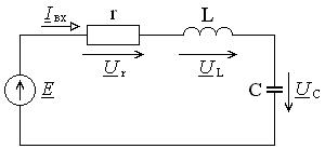
Rice. 15.1. Series oscillating circuit
At the resonant frequency, the reactive component of the impedance becomes zero, that is, the condition is satisfied
From here we obtain a formula for calculating the resonant frequency through the parameters of a series oscillatory circuit
At frequencies less than resonant re active resistance the circuit is negative, that is, it is capacitive in nature, since the resistance of the capacitance more resistance inductance and is predominant. At frequencies above the resonant one, the reactance of the series oscillating circuit is positive and has an inductive nature, since in this case the inductive resistance becomes greater than the capacitance resistance.
Let us transform expression (15.1) taking into account the introduced concept of resonant frequency:
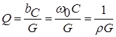
The quantity having the dimension of resistance is called the wave or characteristic impedance of the circuit, and
The ratio of the characteristic resistance to the loss resistance is called the quality factor of the circuit and is denoted by the symbol, and its inverse value is attenuation:
Low-quality circuits have a quality factor less than 50. For medium-quality circuits, the following relation is satisfied: ![]() , for contours good quality –
, for contours good quality – ![]() and for high quality contours – .
and for high quality contours – .
The expression in parentheses in formula (15.4) means Greek letter and is called relative contour detuning
In essence, relative detuning characterizes in relative units the deviation of the frequency of the signal source from the resonant frequency of the circuit.
Taking into account the introduced notation, the resistance formula (15.4) can be written in a more compact form:
The current in a circuit can be found using Ohm's law:
where is the initial phase emf source, ![]() – impedance phase in another form of recording.
– impedance phase in another form of recording.
At the resonant frequency the current is maximum and equal to
Normalized amplitude-frequency response (AFC)
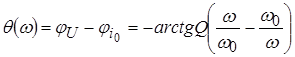
and phase-frequency characteristics (PFC)
current are shown in Fig. 15.2.
At the resonant frequency, the relative detuning (15.7) is zero. That's why
Consequently, at the resonant frequency, the voltage amplitudes on the inductance and capacitance are equal to each other and are several times greater than the emf amplitude:
Therefore, resonance in a series oscillatory circuit is called voltage resonance. The vector voltage diagram for the circuit at the resonance frequency is shown in Fig. 15.3.
The frequency region at the boundaries of which the current decreases by a factor of its maximum value is called the passband. At the boundaries of the passband, according to formula (15.9), the condition is satisfied
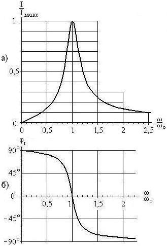
Rice. 15.2. Amplitude-frequency (a) and phase-frequency (b) characteristics of current in a series oscillatory circuit
The discharge of the capacitor cannot occur instantly, because this is prevented by the self-induction EMF that occurs in the inductance element.
In an ideal circuit, the active resistance of which is zero , and therefore there are no losses stored in electric field energy is completely converted into energy magnetic field inductance.
Then the reverse energy transfer occurs. Then the processes are repeated. Thus, undamped electrical oscillations arise, having the shape of a cosine wave. Graphs and are presented in Figure 1, b.
The frequency with which energy oscillates between reactive elements when the source is turned off is called the frequency of free (natural) undamped oscillations of the circuit. Designation: or .
Because in an ideal contour the magnitude of the stresses on L And C are the same, then
![]() ,
,  ,
,
or ![]() , .
, .
In the free oscillation mode, current flows through the circuit elements. The resistance that circuit elements provide to current at the natural frequency is called wave (characteristic ).
This resistance is designated and defined as follows:
![]() , or
, or 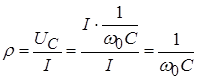 . Because , That
 (Ohm).
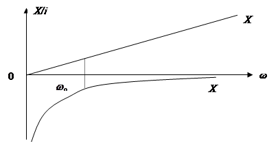
From the last expression it follows that at the natural oscillation frequency the wave impedance is equal to one of reactance(Fig. 2).
In practice, a real AC always has losses; the active resistance is not equal to 0, which leads to the damped nature of free oscillations (Fig. 3).
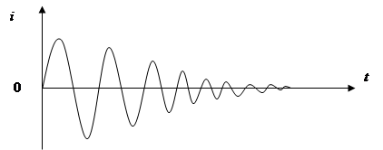
Rice. 3
To characterize the last property, the concept is introduced quality factor contour (contour quality).
Quality factor is an energy parameter and shows how many times reactive power(due to which free oscillations occur) more active:
Note that this definition applies not only to oscillatory circuits, but also to individual parts, for example, inductors, capacitors.
The greater the reactive power, the higher the quality factor and the slower the damping of oscillations and vice versa.
The quality factor of QCs used in communications technology is usually tens to hundreds, and in microwave technology and special devices the quality factor can reach a thousand or more.
It is generally accepted that if: – KK low quality factor ,
– QC medium quality factor ,
– KK high quality factor .
Practically implement L.C. a circuit with a quality factor over 400 is difficult due to the low quality factor of the inductors (they are the ones who determine the quality of the circuit).
Conclusion: The considered parameters , and for oscillatory circuits are one of the main ones, because they depend on the primary parameters, and they are called secondary parameters of the circuit .
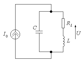
2. Possible modes of steady-state harmonic oscillations in a parallel oscillatory circuit
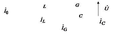
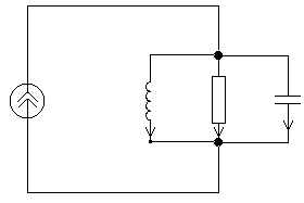
Parallel oscillatory circuit called a circuit composed of elements of inductance, capacitance and resistance connected in parallel. The circuit diagram is shown in Figure 4.
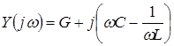
Let's find the complex conductivity of the circuit:
where: – active component of conductivity,
– reactive component of conductivity.
From the formula it follows that, depending on the ratio and in a parallel circuit, 3 modes are possible:
1), i.e. And .
Let's construct a vector diagram for this case, putting the initial phase of the voltage on the circuit equal to 0 (Fig. 5)
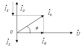
As can be seen from the vector diagram, the current in the circuit leads the voltage by a certain angle, which is a sign capacitive mode .
Conclusion capacitive oscillation mode and the current in the circuit leads the voltage.
Having constructed a vector diagram in a similar way (Fig. 6), we will make sure that the current in the circuit will now lag behind the voltage by a certain angle, which is a sign inductive mode .
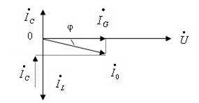
Conclusion: When in parallel circuit is set inductive oscillation mode, and the current in the circuit lags behind the voltage.
The conductivity of the circuit in this case is equal to the active conductivity G . The circuit is active, i.e. the current is in phase with the voltage on the circuit and numerically equal to current through conductivity (Fig. 7).
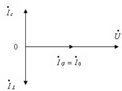
This mode is called current resonance and has important practical significance.
The analysis shows that the oscillation mode in a parallel circuit is determined by the ratio of reactive conductivities and .
Any of the considered modes can be obtained in several ways: by changing the generator frequency, inductance and capacitance.
Conclusion: The values of the GK modes in the circuit allow us to qualitatively analyze the processes taking place in the circuits, making the appropriate engineering calculations.
3 . Current resonance
1) Resonance frequency
It is shown above that current resonance occurs at a frequency at which:
where ![]() .
.
Those. the resonant frequency is equal to the natural frequency of the circuit. Change is achieved by change L or C(more often).
2)Circuit impedance
At the resonant frequency, from where 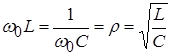 (Ohm), i.e. the characteristic impedance of the circuit is equal to the resistance of one of the reactive elements.
Typically, the characteristic impedance of PCs used in electrical circuits is on the order of several hundred Ohms (100500).
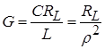
3)Circuit quality factor
By definition 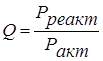 , Where,
 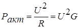 hence
hence 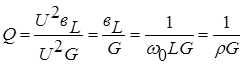 .
.
Because at the resonant frequency, the numerical values of conductivity and are the same, then the quality factor can be calculated using the following formula:
 , That.
 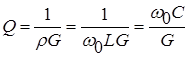 .
.
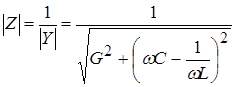
4) Resonant circuit resistance, currents in branches at resonance
 because at resonance, then
 ![]() , i.e. The resistance of the circuit at resonance is purely active and greatest in value.
, i.e. The resistance of the circuit at resonance is purely active and greatest in value.
Indeed, the total resistance of the circuit is equal to:
 at , and .
Let us determine the relationship between the source current and the current through the reactive element:
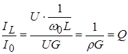 , i.e. .
Similarly, it can be shown that.
Conclusion: At resonance, the currents in the branches of the parallel CC are maximum and in Q once more current source. This explains the name of the mode - current resonance .
At the resonant frequency, the master current source is closed through the conductivity element of the circuit. The currents in the reactive elements of the circuit mutually compensate each other relative to the external circuit of the circuit, or, similarly, at the resonant frequency, the circular current is closed through the reactive elements of the circuit. At the same time, and is the largest in magnitude. At resonance, the voltage on the circuit is maximum (). It is for this reason that the parallel CC is tuned to the resonant frequency.
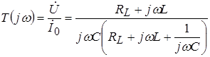
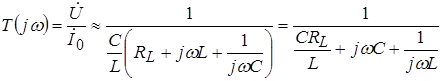
4. Complex parallel loop transfer functions
Expressions for the frequency characteristics of a parallel oscillatory circuit relative to voltage can be obtained from the following complex transfer function:
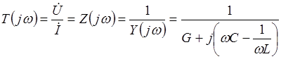 .
.
Let's transform the denominator:
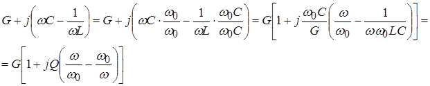 That.
That. 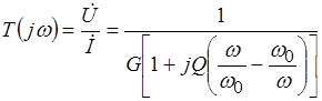 .
.
Here the frequency-dependent factor is  called relative detuning
. The work is called generalized contour detuning
.
called relative detuning
. The work is called generalized contour detuning
.
Taking this into account: 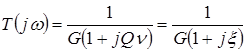 .
.
From the expression 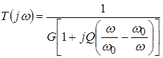 we get
frequency response
: 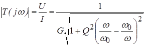 ,
,
And FCHH:
 .
.
Frequency response is called resonant characteristic parallel to the oscillatory circuit. This characteristic has its maximum value at the resonant frequency ( ![]() ),
), ![]() .
.
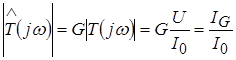
The resonant characteristic of a circuit is usually normalized relative to its maximum value. Normalized resonant characteristic: i.e. the ratio of the voltage amplitude at a given frequency to the voltage amplitude at resonance:
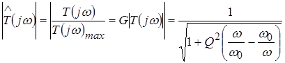 .
.
The normalized resonant characteristic is nothing more than the frequency response of the circuit relative to the current in the active resistance element.
 .
.
Let us find an approximate expression for the frequency characteristics of the oscillatory circuit with the equivalent circuit shown in Figure 8.
It differs from the equivalent circuit of a parallel oscillatory circuit in that in it the losses in the inductance of the real circuit are taken into account by a resistance connected in series with the inductance. For the considered circuit:
 .
.
In the frequency range in which the reactive component of the inductor resistance is slightly larger than the active component of its resistance, the term in the numerator of the last expression can be neglected.
Then approximately:
 .
.
The resulting approximate formula does not differ from the strict formula for the complex transfer function of a parallel circuit with the same inductance values L and containers WITH and with active conductivity:
 .
.
Conclusion
The considered modes of steady-state harmonic oscillations in a parallel oscillatory circuit make it possible to give a physical explanation of the frequency response and phase response. The frequency characteristics of a parallel oscillatory circuit remain approximately true also for other equivalent circuits of real oscillatory circuits, if you are interested in the behavior of the characteristics in a relatively narrow frequency band.
Literature used to prepare for the lecture: Beletsky A.F. Linear theory electrical circuits. – M.: Radio and Communications, 1986. (Textbook); Bakalov V.P. and others. Theory of electrical circuits. – M.: Radio and Communications, 1998. (Textbook); Kachanov N.S. and others. Linear radio engineering devices. M.: Military Publishing House, 1974. (Textbook); V.P. Popov Fundamentals of circuit theory - M.: graduate School, 2000.(Textbook)
14 Series oscillating circuit
As is known, the simplest resonant (or oscillatory) circuits are series and parallel oscillatory circuits. Let's consider a circuit consisting of an inductor and a capacitor connected in series (Fig. 1). When such a circuit is exposed to an alternating (in the simplest case harmonic) voltage, an alternating current will flow through the coil and capacitor, the magnitude (amplitude) of which can be calculated according to Ohm’s law: I = U/|X Σ | , where |Х Σ | -modulus of the sum of the reactances of a series-connected coil and capacitor. In Fig. Figure 2 shows the dependences of the reactances of the coil X L and the capacitor X C on the circular frequency ω, as well as a graph of the dependence of their algebraic sum X Σ on the frequency ω. The last graph, in fact, shows the dependence of the total reactance of the circuit shown in Fig. on the frequency. 1. From this graph it is clear that at a certain frequency ω=ω p, at which the reactances of the coil and capacitor are equal in magnitude, the total resistance of the circuit becomes zero. At this frequency, a maximum current is observed in the circuit, which is limited only by ohmic losses in the inductor (i.e., the resistance of the coil winding wire) and the internal resistance of the current source (generator). The frequency at which the phenomenon under consideration, called resonance in physics, is observed is called the resonant frequency or the natural frequency of oscillations of the circuit, and the circuit itself, shown in Fig. 1 is usually called a series oscillatory circuit. Also from Fig. 2 it can be seen that at frequencies below the resonance frequency the reactance of the series oscillatory circuit is capacitive in nature, and at higher frequencies it is inductive. As for the resonant frequency itself, it can be calculated using the well-known Thomson formula: ω р = 1/√(LC).
Rice. 1 Series oscillating circuit
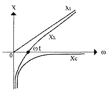
Rice. 2 Dependences of the reactance of the coil X L and capacitor X C on the angular frequency ω
Figure 3 shows an equivalent circuit of a series resonant circuit taking into account ohmic losses r, connected to an ideal harmonic voltage generator with amplitude U. The total resistance (impedance) module of such a circuit is determined as follows: |z| = √(r 2 +|X Σ | 2), where |X Σ | = ωL-1/ωC. It is obvious that at the resonant frequency, when the values of the reactances of the coil X L = jωL and the capacitor X C = -j/ωС are equal in magnitude, the value |X Σ | goes to zero (hence, the circuit resistance is purely active), and the current in the circuit is determined by the ratio of the generator voltage amplitude to the resistance of ohmic losses: I= U/r. In this case, the same voltage U L =U C =I|X L |=I|X C | drops on the coil and on the capacitor, in which reactive electrical energy is stored. At any other frequency other than the resonant one, the voltages on the coil and capacitor are not the same - they are determined by the amplitude of the current in the circuit and the values of the reactance modules |X L | and |X C | Therefore, resonance in a series oscillatory circuit is usually called voltage resonance. Taking into account the above notation for the circuit impedance, we can give a frequently used definition of the resonant frequency: the resonant frequency of the circuit is the frequency at which the resistance of the circuit is purely active (resistive) in nature.
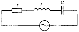
Rice. 3 Equivalent circuit of a series resonant circuit
One of the most important parameters of an oscillatory circuit (except, of course, the resonant frequency) is its characteristic resistance ρ and quality factor Q. The characteristic resistance of the circuit ρ is the value of the modulus of the reactance of the capacitance and inductance of the circuit at the resonant frequency: ρ = |X L | =|X C | at ω =ω r. In general, the characteristic impedance can be calculated as follows: ρ = √(LC). Characteristic resistance ρ is a quantitative measure of the energy stored by the reactive elements of the circuit - the coil (magnetic field energy) W L = (LI 2)/2 and the capacitor (electric field energy) W C = (CU 2)/2. The ratio of the energy stored by the reactive elements of the circuit to the energy of ohmic (resistive) losses over a period is usually called the quality factor Q of the circuit, which literally means “quality” in English. The reciprocal of the quality factor d=1/Q is called the circuit attenuation. To determine the quality factor, they usually use the formula Q = ρ/r, where r is the resistance of the ohmic losses of the circuit, which characterizes the power of the resistive (active losses) of the circuit P = I 2 r. The quality factor of real oscillatory circuits made on discrete inductors and capacitors ranges from several units to hundreds or more. The quality factor of various oscillatory systems built on the principle of piezoelectric and other effects (for example, quartz resonators) can reach several thousand or more.
|
|
|
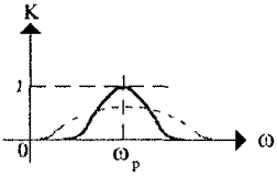
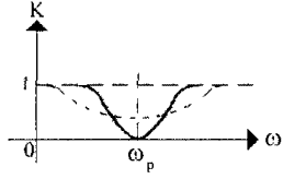
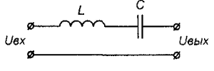
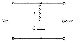
Frequency properties various circuits in technology it is customary to evaluate using amplitude-frequency characteristics (AFC). In Fig. 4a and fig. Figure 4b shows two simple two-port networks containing a series oscillatory circuit. The frequency response of these circuits is shown (shown by solid lines) in Fig. 5a and fig. 5b respectively. The value of the circuit's voltage transfer coefficient K, showing the ratio of the circuit's output voltage to the input voltage, is plotted along the vertical axis. For passive circuits (i.e. those containing amplification elements and energy sources), the value of K never exceeds one. It is obvious that the circuit resistance in Fig. 4a, the alternating current will be minimal at an impact frequency equal to the resonant frequency of the circuit. In this case, the circuit transmission coefficient is close to unity (determined by ohmic losses in the circuit). At frequencies very different from the resonant one, the resistance of the circuit to alternating current is quite high, and therefore the transmission coefficient of the circuit will drop to almost zero. At resonance in the circuit shown in Fig. 4b, the source of the input signal turns out to be virtually short-circuited by a small circuit resistance, due to which the transmission coefficient of such a circuit at the resonant frequency drops to almost zero (again due to the presence of finite loss resistance). On the contrary, at input frequencies significantly distant from the resonant one, the circuit transmission coefficient turns out to be close to unity. The property of an oscillatory circuit to significantly change the transmission coefficient at frequencies close to the resonant one is widely used in practice when it is necessary to isolate a signal with a specific frequency from many unnecessary signals located at other frequencies. Thus, in any radio receiver, tuning to the frequency of the desired radio station is ensured using oscillatory circuits. The property of an oscillatory circuit to select one from many frequencies is usually called selectivity or selectivity. In this case, the intensity of the change in the transmission coefficient of the circuit when the frequency of influence is detuned from resonance is usually estimated using a parameter called the passband. Most often, the passband is taken to be the frequency range within which the decrease (or increase, depending on the type of circuit) of the transmission coefficient relative to its value at the resonant frequency does not exceed 0.707 (3 dB).
Dotted lines in Fig. 5a and fig. Figure 5b shows the frequency response of exactly the same circuits as in Fig. 4a and fig. 4b, respectively, the oscillatory circuits of which have the same resonant frequencies as in the case discussed above, but have a lower quality factor (for example, the inductor is wound with a wire that has a high resistance to direct current). As can be seen from Fig. 5a and fig. 5b, in this case the circuit bandwidth expands and its selective properties deteriorate. Based on this, when calculating and designing oscillatory circuits, one must strive to increase their quality factor. However, in some cases, the quality factor of the circuit, on the contrary, has to be underestimated (for example, by including a small resistor in series with the inductor), which avoids distortion of broadband signals. Although, if in practice it is necessary to isolate a sufficiently broadband signal, selective circuits, as a rule, are built not on single oscillatory circuits, but on more complex coupled (multi-circuit) oscillatory systems, incl. multi-section filters.