The supply voltage of the LEDs in the lamp. Repair of LED lamps, device, electrical circuits
Repair of 220-volt LED lamps, if desired, can be done at home, but for this you certainly need to have a soldering iron and a multimeter available.
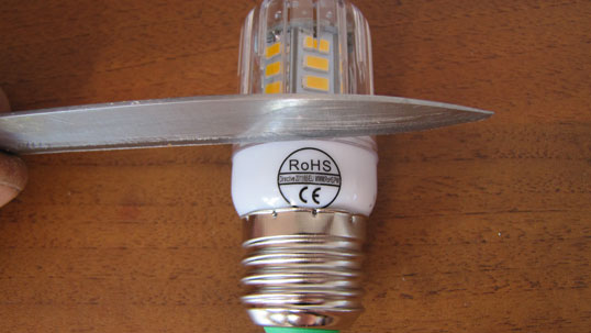
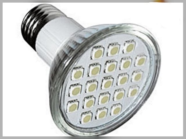
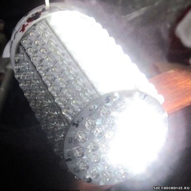
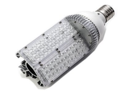
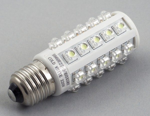
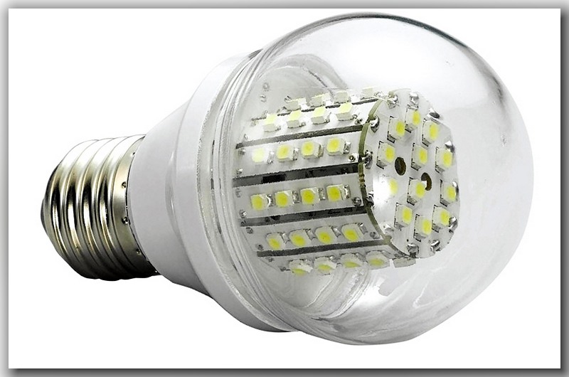
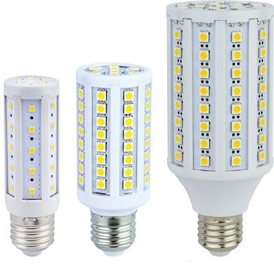
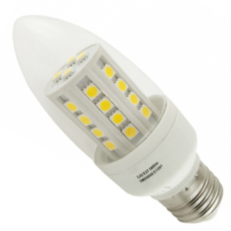
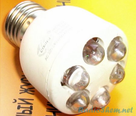
LED lamps of this type in English are called "LL-CORN", which means (corn lamp), in appearance it really looks like an ear of corn. These "ears" are available in many types. It is difficult to choose really high quality products. Most of these bulbs are made in China and are fakes, but this article will not be about the fight against counterfeit products, but we will talk about the repair of LED corn lamps.
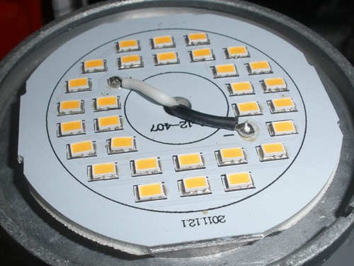
Lamps of this type as in the photo are produced for 24, 30, 36, 48, 56, 69, 72 LEDs. These lamps are currently equipped with SMD5730 or SMD5733 LEDs. Their data:
SMD5730 - dimensions are indicated in the title 5.7 mm. by 3.0 mm. Power - 0.5 watts. Voltage 3.4 volts. Current 150 mA. Luminous flux 30 - 45 lumens.
SMD5733 - dimensions are indicated in the title 5.7 mm. 3.3 Power - 0.5 watts. Voltage 3.4 volts. Current 150 mA. Luminous flux 35 - 50 lumens. But it must be said that LEDs manufactured in China often do not meet the declared characteristics.
If the LED lamp stops shining, then it does not need to be thrown away immediately, repairing such a lamp is not difficult and can be done by almost anyone who knows how to hold a soldering iron in their hands. But before repairing a lamp, you need to make sure that the lamp is receiving power where it stood. This means that in place of the twisted lamp you need to screw in another one and make sure that it is the lamp that does not work, and not the lamp itself.
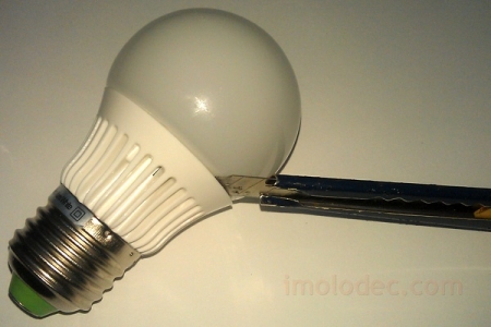
For repairs, you need to get to the insides, and then the question arises how to open the LED lamp? The answer is simple - with an ordinary kitchen knife. You need to insert the knife into the place where the lamp body is connected to the protective transparent casing and turn until the casing groove comes out of the casing protrusion.
The cover will pop out with a slight click.
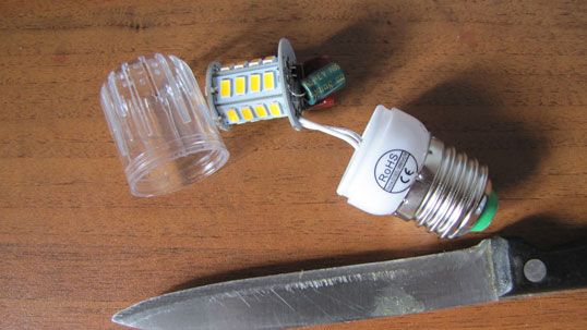
The whole "filling" of the lamp opens before us. First of all, we inspect everything inside and make sure that the soldering of the parts is of high quality (if not, then we solder the questionable places). If there are blackened parts, then we change them to similar ones.
To determine the ratings of parts, the article below provides a general diagram for similar lamps and lists the ratings of parts, depending on the power of the lamp. If there are blackened LEDs, then they definitely must be replaced with exactly the same ones. When replacing LEDs, be sure to pay attention to the polarity. If you confuse plus and minus, it won't work.
If you have a powerful soldering iron, then to solder small LEDs, you need to wind a piece of copper wire of a suitable diameter on the tip of the soldering iron and solder with it.
Swollen capacitor - change. There is a crack in the part - we change it. Crack on the PCB - solder the jumper to the circuit tracks or clean the varnish on both sides of the crack and apply a drop of tin with a soldering iron. If there are no suitable parts, then we leave this burned-out light bulb as a donor for future repairs.
It happens that appearance the parts are normal, but it has internal damage. In this case, you cannot do without a multimeter. We check the capacitors for breakdown, and the resistors for an open circuit. There are few parts in the circuit of LED lamps and it is not difficult to check them all.
The exception is lamps, where the power is implemented on drivers from microcircuits. Driver repair led lamp, consisting of micro components at home, you can do it, but in a limited way, and only professionals can do it. The circuit in our lamp is simple.
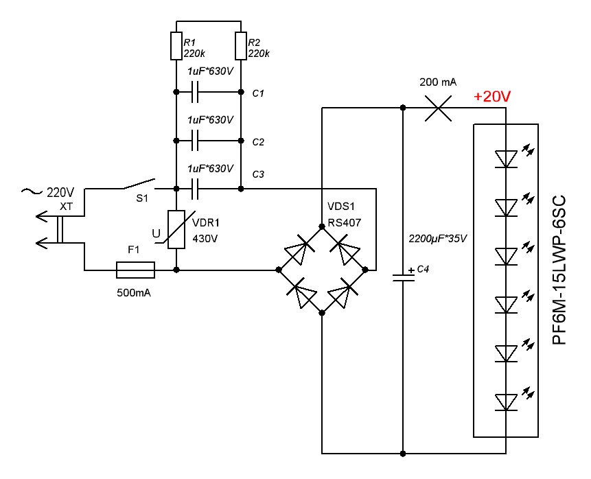
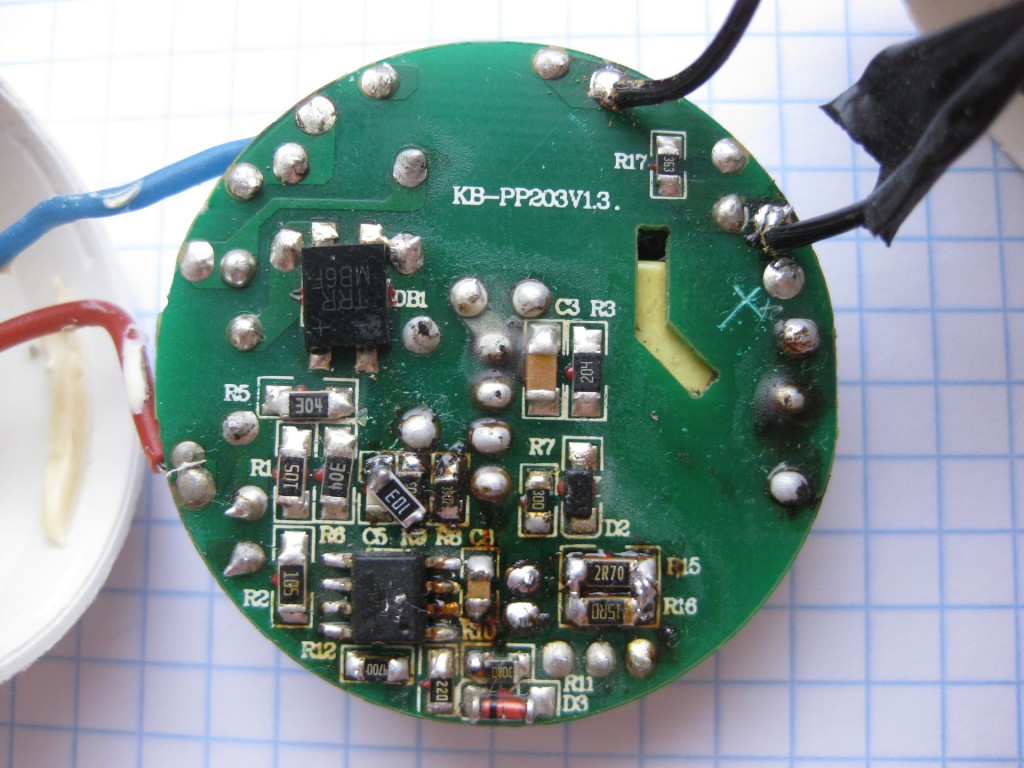
All bulbs in the series that we are considering have the same circuit. Only the number of LEDs and the ratings of some elements differ. For repairs, it is important to know how the circuit works and what role the parts play. Start over.
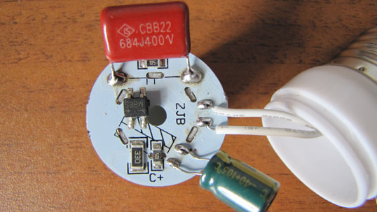
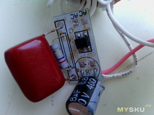
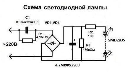
Capacitor C1 is a quenching capacitor and can be replaced in exactly the same way as in a 400 volt lamp.
For a 24 LED lamp, it is 0.56 microfarad. For a 30 LED lamp - 0.68 uF. 36 - 48 LEDs - 0.82 uF. 56 - 69 LEDs - 1.2 uF. Designated as 564J400v, 684J400v, 824J400v, L105J400v, respectively.
Capacitor C2 serves to smooth out the ripple of the current rectified by the diode assembly and can be replaced with any polar capacitor from 2.2 to 10 microfarads with voltage from 100 to 400 volts. But it is better to take these denominations to the maximum. The higher the value, the less LED flickering will be. Conduct an experiment with a phone camera by pointing the lens at an on LED light.
Resistors R1 and R2 serve to discharge the capacitors, in parallel with which they are connected, and can be replaced by any one from 500 kilo ohms to 1.5 mega ohms.
The diode assembly is used by MB6S and can be replaced with any similar one, or you can use four diodes, for example 1N4007 or any similar, connected in a bridge circuit.
Resistor R3 limits the current of the LEDs and its value depends on the number of them in the lamp. 24 - 30 LEDs - 33 ohms. 36 LEDs - 36 ohms. 48 LEDs - two connected in parallel, 100 ohms each, it turns out 50 ohms. 56 LEDs - 100 ohms. 69 LEDs - two parallel to 390. You can replace the same power or more. The resistance of this resistor determines the current that passes through the LEDs and, therefore, the brightness of their glow. If the value of the resistor is taken less, then the glow will increase, but the service life of the LED will significantly decrease and vice versa.
Now you yourself can do the repair of LED lamps for 220 with your own hands.
Good luck in your business.
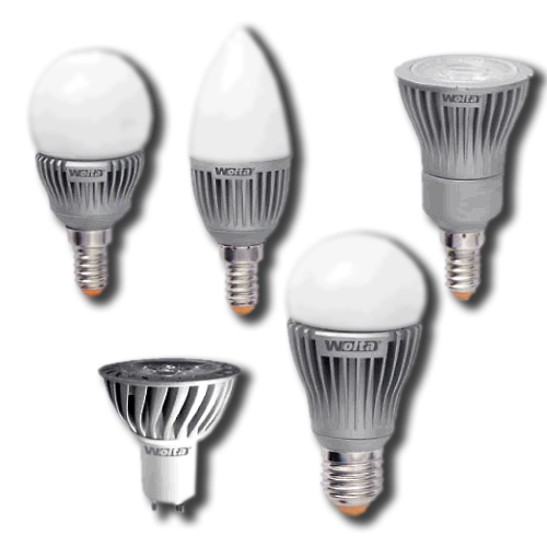
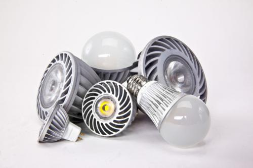
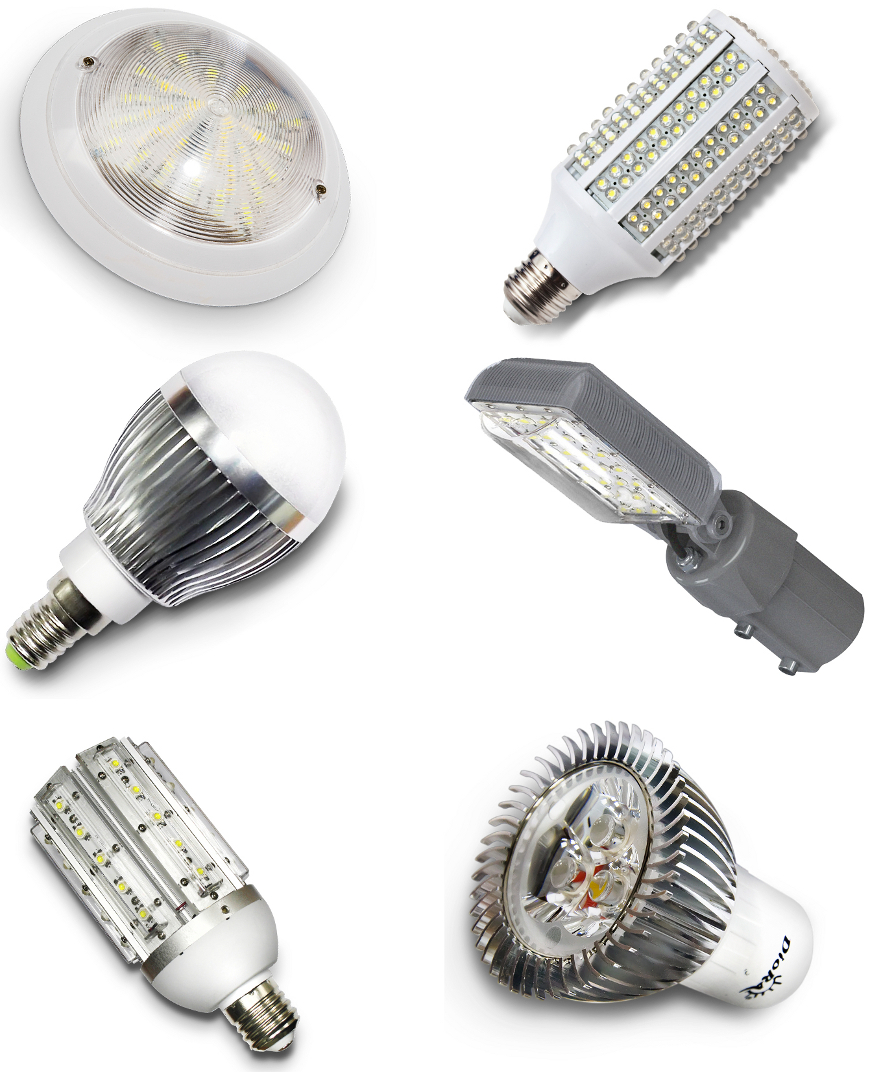
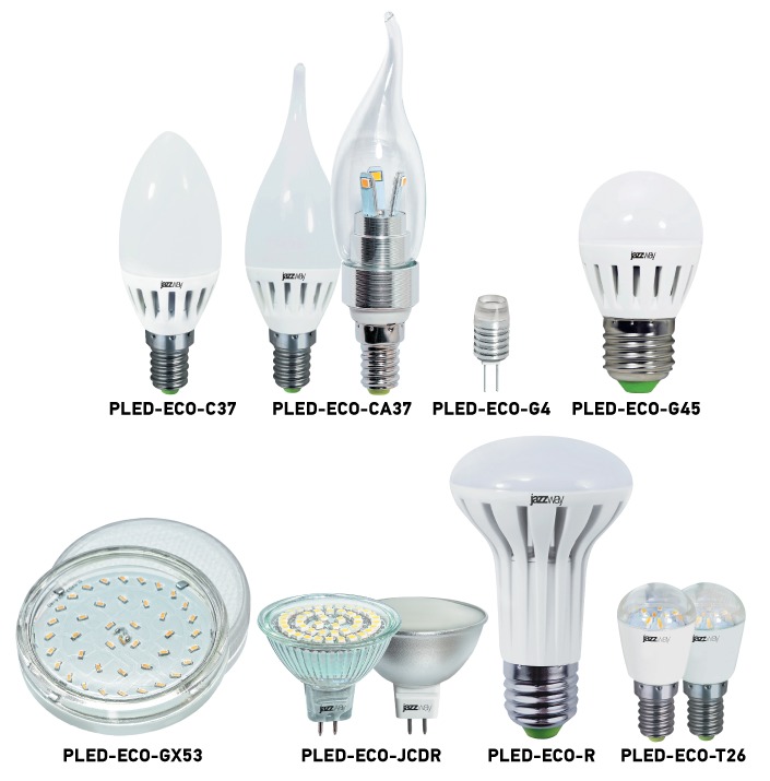
In the photo you can see a lot of LED lamps. I got them as a gift. There was an opportunity to study the structure of these lamps, electrical circuits, as well as repair these lamps. The most important thing is to find out the reasons for the failure, since the service life indicated on the box does not always coincide with the service life.
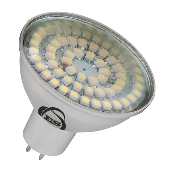
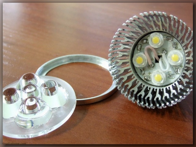
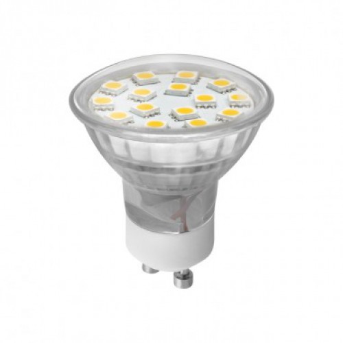
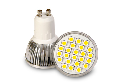
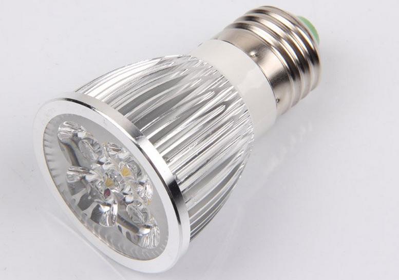
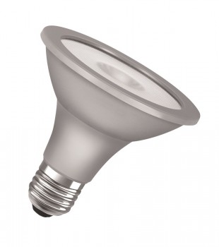
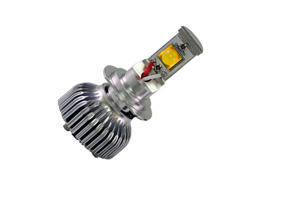
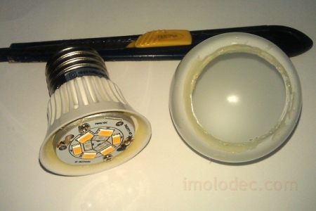
Lamps of the MR-16 type can be disassembled without any effort.
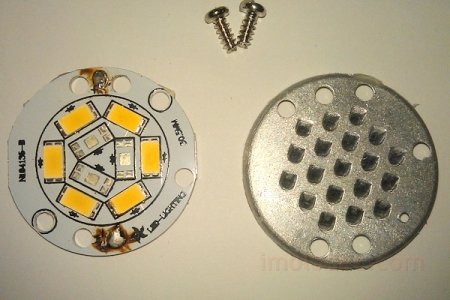
Judging by the label, the lamp has model MR-16-2835-F27. Its body contains 27 SMD LEDs. They emit 350 lumens. This lamp is suitable for network connection alternating current 220-240 V. Power consumption is 3.5 W. Such a lamp glows white, the temperature of which is 4100 degrees Kelvin and creates a narrowly directed flux due to the flux angle equal to 120 degrees. The used type of base is "GU5.3", which has 2 pins, the distance between which is 5.3 mm. The body is made of aluminum, the lamp has a removable base, which is fastened with two screws. The glass that protects the lamp from damage is glued to the glue at three points.
How to disassemble LED lamp MR-16
To identify the cause of the breakdown, it is necessary to disassemble the lamp housing. This is done effortlessly.
As you can see in the photo, a ribbed surface is visible on the case. It is designed for better heat dissipation. We insert a screwdriver into one of the ribs and try to lift the glass.
Happened. You can see the printed circuit board, it is glued to the case. Prying it off with a screwdriver, it detaches.
Repair of LED bulbs MR-16
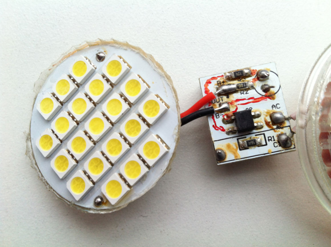
Among the first, the lamp was dismantled, inside of which the LED burned out. The printed circuit board, which is made of fiberglass, is burned through.
This lamp is suitable as a "donor", from which the necessary spare parts will be taken to repair other lamps. The LEDs on the remaining 9 lamps also burned out. Since the driver is intact, the LEDs are the cause of the breakdown.
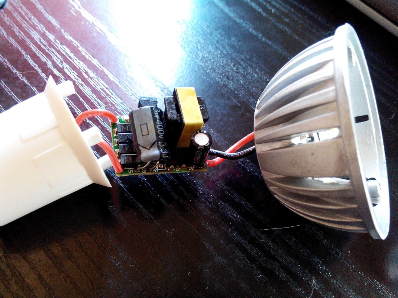
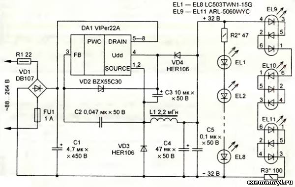
Electrical circuit of LED lamp MR-16
To reduce the lamp repair time, it is necessary to create its electrical circuit. It's pretty straightforward.
Attention! The circuit is galvanically connected to the mains phase. It is prohibited to use it to power any devices.
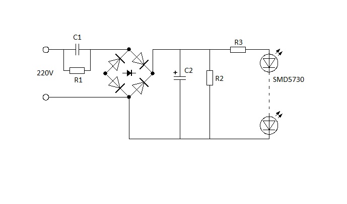
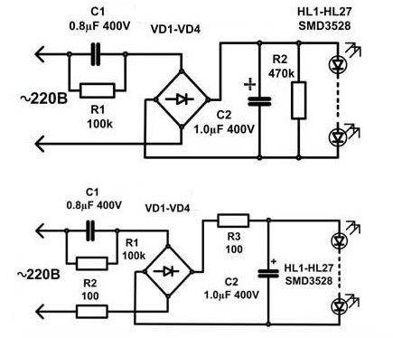
How does the circuit work? A voltage of 220 V is supplied to the diode bridge VD1-VD4 through the capacitor C1. Then it is fed to the LEDs HL1-HL27, which are connected in series in the circuit. The number of LEDs can be about 80 pieces. Capacitor C2 (the larger the capacitance, the better) is a rectified voltage ripple smoother. It eliminates the flicker of 100 Hz light. To discharge C1, R1 was set. This is necessary in order to exclude electric shock when replacing the lamp. C2 is protected against R2 breakdown in case of an open circuit. R1, R2, as such, do not accept work in the circuit.
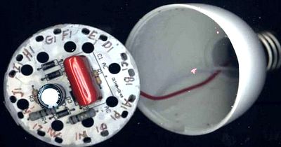
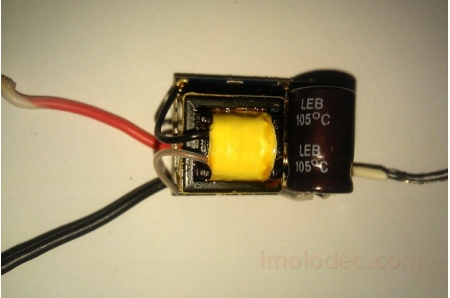
C1 - red, C2 - black, diode bridge - body with four legs.
Classic driver circuit for LED lamps with power up to 5 W
The wiring diagram of the lamps has no protection elements. You will need a 100-200 ohm resistor, and preferably two. One will be installed in the connection circuit, the second will serve as protection against current surges.
Above is a diagram with protective resistors. R3 protects the LEDs and C2 the capacitor, R2 in turn protects the diode bridge. This driver is perfect for lamps less than 5W. It will easily power a lamp with 80 SMD3528 LEDs. If you need to reduce or increase the current, manipulate the capacitor C1. To eliminate flickering, increase the capacity C2.
The efficiency of such a driver is less than 50%. For example, a MR-16-2835-F27 lamp requires a 6.1 kΩ resistor with a power of 4 W. Then the driver will consume more power than the LEDs. Due to the large release of thermal energy, it will not work to place it in a small lamp housing. In this case, you can separately make a case for this driver.
It should be remembered that the efficiency of the lamp directly depends on the number of LEDs.
Finding faulty LEDs
After the protective glass has been removed, the LEDs can be inspected. If the slightest black speck is found on the surface of the LED, it is out of order. Inspect the soldering points, inspect the quality of the leads. Four poorly soldered LEDs were found in one of the lamps
LEDs with black dots have been marked with a cross. On visual inspection, the LEDs may be intact. Therefore, you need to call them with a tester. To check, you need a voltage of a little more than 3 V. A rechargeable battery, battery, power supply will do. A 1 kΩ current-limiting resistor is connected in series behind the power supply.
We touch the LED with the probes. In one direction, the resistance should be small (the LED can glow), in the other - it should be equal to tens of megohms.
During the test, it is necessary to fix the lamp. The bank can come to the rescue.
It is possible to test the LED without special devices if the device driver is intact. Voltage is applied to the lamp base, the LED leads are short-circuited with tweezers or a piece of wire.
If all LEDs are visible, the shorted one is faulty. But this method is suitable if 1 LED in the circuit is out of order.
If multiple LEDs are broken in the circuit, the lamp will light. Only its luminous flux will decrease. Just short-circuit the pads where the LEDs have been soldered.
Other malfunctions of LED lamps
If during the check it turned out that the LEDs are working, then the matter is in the driver or the soldering point.
Cold soldering of the conductor was found in this lamp. Soot from poor soldering settled on the board tracks. To remove soot, a cloth moistened with alcohol was needed. The wire was dropped, tinned and soldered. This lamp is working.
Of all the lamps, one had a driver failure. The diode bridge has been replaced with 4 "IN4007" diodes, which are rated for 1 A and 1000 V reverse voltage.
Soldering SMD LEDs
To replace a faulty LED, it is necessary to solder it without damaging the printed conductors. This can be done with difficulty with an ordinary soldering iron; it is better to put a tip made of copper wire on the soldering iron.
When soldering the LED, observe the polarity. Install the LED to the soldering point, take a 10-15 W soldering iron and warm up its ends.
If the LED is burnt and the board is charred, this area should be cleaned. Since it is a conductor. If the site has stratified, the LED is mono soldered to the "neighbors". This is done if the tracks lead exactly to them. Just take a piece of wire, twist it two or three times and solder it.
Analysis of the causes of failure of LED lamps MR-16-2835-F27
According to the table, we can conclude that lamp breakdowns often occur due to the failure of LEDs. The reason for this is the lack of protection in the circuit. Although there is a place for a varistor on the board.
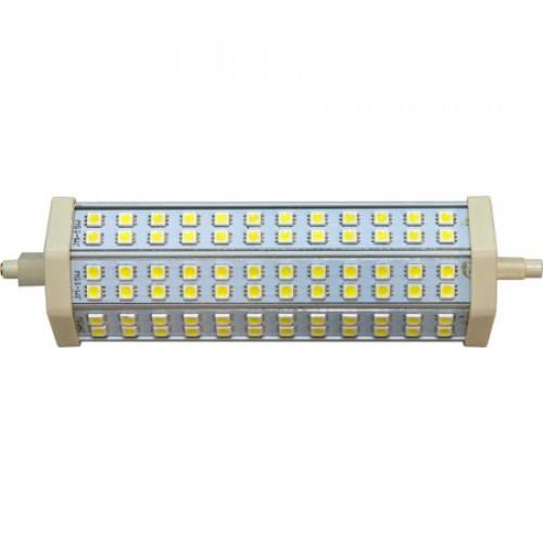
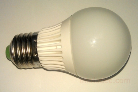
Repair of LED lamp series "LL-CORN" (corn lamp) E27 4.6 W 36x5050SMD
The technology for repairing a corn lamp is different from repairing the lamp shown above.
Repairing such a lamp is simple, since the LEDs are located on the body. And no unnecessary actions are required for dialing. This lamp was disassembled purely out of interest.
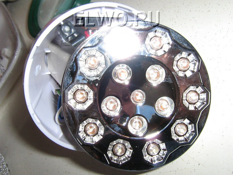
The technique of checking "corn" does not differ from the above. Only in the case of these lamps there are 3 LEDs. When dialing, all 3 should light up.
If one of the LEDs is damaged, short-circuit it or solder a new one. This will not affect the lamp life. The lamp driver has no decoupling transformer. Therefore, any touch of the LED tracks is unacceptable.
If the LEDs are intact, it's the driver. In order to inspect it, it is necessary to disassemble the case.
To get to the driver, you need to remove the bezel. Pry it off with a screwdriver at the weakest point, it should come off.
The driver has the same circuit as our first lamp with the difference that C1-1µF, C2- 4.7 µF. The wires are long, so the driver can be pulled out without effort. After the work on replacing the LED, the bezel was mounted on the Moment glue.
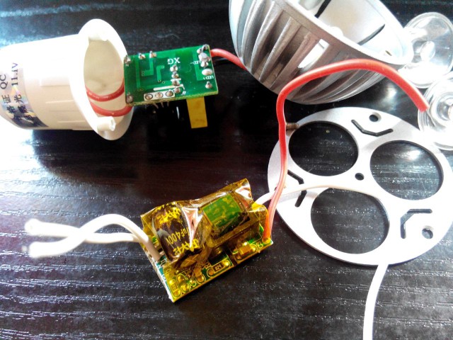
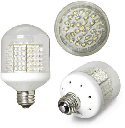
Repair of LED lamp "LL-CORN" (corn lamp) E27 12 W 80x5050SMD
Repair of a 12 W lamp is done in the same way. No burned-out LEDs were found on the case, so I had to open the case to inspect the driver.
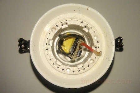
There are problems with this lamp. The driver wires were too short and the base had to be removed.
The plinth is made of aluminum. It was attached to the body by punching. Therefore, it was necessary to drill out the attachment points with a drill with a diameter of 1.5 mm. Further, the base was pry off with a knife and removed. The wires inside had to be eaten.
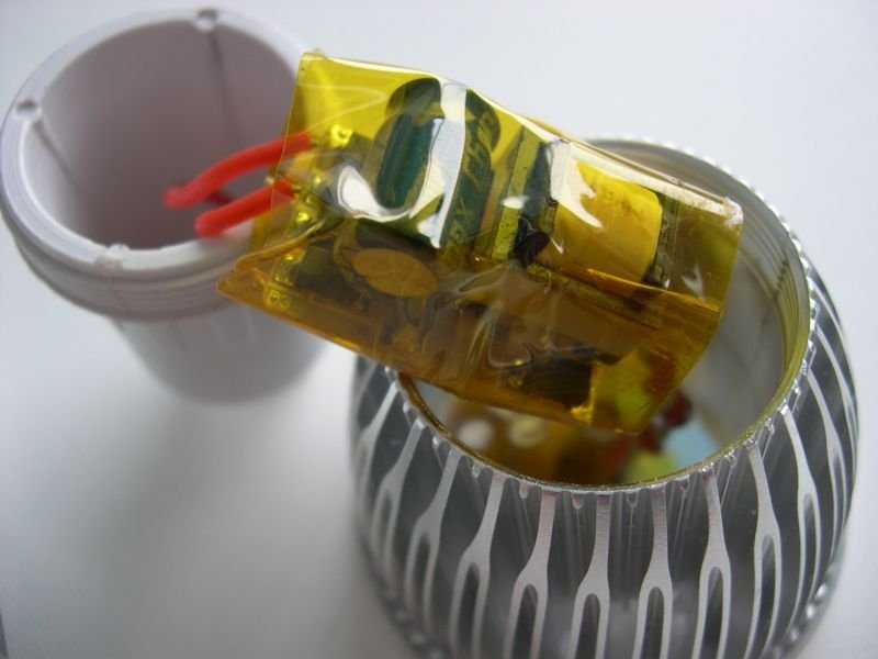
Inside there were 2 identical drivers, each of which powered 43 diodes.
The driver is wrapped in a heat-shrinkable tube that had to be cut.
After troubleshooting, the same tube is pushed onto the driver and squeezed with a plastic tie.
The driver circuit implies protection. C1 protects against surges, R2, R3 against current surges. During testing, R2 breaks were noticed. Most likely, a voltage exceeding the norm was applied to the lamp. There was no 10 ohm resistor, so a 5.1 ohm resistor was soldered. The lamp lit up. Next, it was necessary to connect the driver to the base.
First, the short wires were replaced with longer ones. The drivers were connected by supply voltage. To attach the wires to the threaded part of the base, you need to clamp them between the plastic case and the base.
How to connect to the center contact? Aluminum is not soldered, so the wire was soldered to a brass plate, in which a hole for M 2.5 was drilled. A similar hole was drilled in the contact. All this was twisted with a screw. Then the base was put on and screwed to the lamp body. The lamp was serviceable.
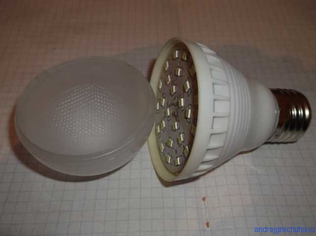
Repair of LED lamp series "LLB" E27 6 W 128-1
The lamp design is ideal for refurbishment. The case is easily disassembled.
Hold the base with one hand and turn the protective cover counterclockwise with the other.
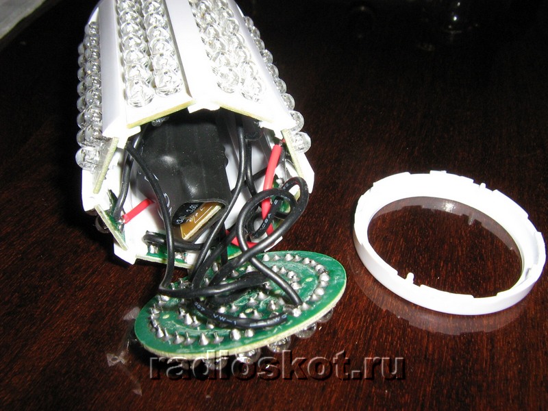
There are five rectangular boards under the case, on which LEDs are soldered. The rectangle is soldered to a circular board that houses the driver circuit.
To access the LED pins, you need to remove one of the covers. To facilitate the work, it is better to remove the board located at the driver voltage points. The photo shows that this wall is parallel to the capacitor body and is at a maximum distance from it.
To remove the board, you need to warm up the soldering points with a soldering iron. Then, to remove it, we warm up the solder on the round board and it is disconnected.
Access for checking breakages is open. The driver follows a simple scheme. Checking his rectifier diodes, as well as all the LEDs (there are 128 of them in this lamp) did not show a problem.
When I examined the soldering points, I found that they were missing at some points. These places were soldered, besides that I connected the printed circuit boards in the corners.
When you look at the light, these paths are clearly visible and you can easily determine where which path is.
Before assembling the lamp, it was necessary to test it. For this, a jumper was installed on the board, the soldered part of the lamp was connected to the power source with two temporary wires.
The lamp lit up. It remains to solder the board in its original place and assemble the lamp.
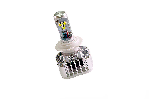
Repair of LED lamp series "LLB" LR-EW5N-5
In appearance, the lamp is made with high quality. The body is aluminum, the design is beautiful.
The lamp is securely assembled. Therefore, in order to disassemble it, you need to remove the protective glass. To do this, insert the end of the screwdriver between the radiator. The glass is fixed here without glue, with a shoulder. You need to lean on the end of the radiator with a screwdriver and lift the glass up, using the screwdriver as a lever.
The tester showed no LED breakage. So it's all about the driver. To get to it, you need to unscrew 4 screws.
![]()
But I was overtaken by failure. The heatsink plane was located behind the board. It is greased with a paste that conducts heat. I had to collect everything that I untwisted. I decided to disassemble the lamp from the base side.
In order to remove the base, it was necessary to drill out the punching places. But he didn't act. As it turned out, it was screwed to the plastic.
The radiator needed to be separated from the plastic adapter. To do this, I washed it down with a hacksaw in the place where the plastic was attached to the radiator. Then, by turning a screwdriver, the parts were separated from one another.
The leads were taped from the LED board, which made it possible to work with the driver. Its circuitry was more complex than other drivers. Upon examination, a swollen 400 V 4.7 µF capacitor was found. It has been replaced.
Schottky diode "D4" type SS110 was damaged. It is located at the bottom left in the photo. It was replaced by the analogue "10 BQ100" having 1A and 100V. The light came on.
Repair of LED lamp series "LLB" LR-EW5N-3
The lamp is similar to the "LLB" LR-EW5N-5, but its design has been changed.
The protective glass is attached with a ring. If you pick up the junction of the ring and glass, it can be easily removed.
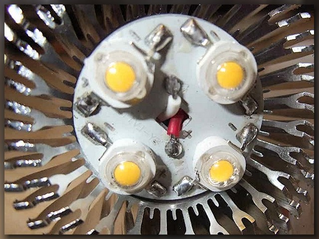
The printed circuit board is made of aluminum. There are nine crystal LED light-emitting diodes (3 pieces) on it. The board is attached to the heatsink with 3 screws. Checking did not reveal any problems with the LEDs. So it's the driver. The experience of repairing a similar lamp has shown that it is better to immediately unsolder the wires that come from the driver. The lamp was disassembled from the side of the base.
The ring connecting the base and the radiator was removed with great effort. In this case, the piece broke off. And all due to the fact that it was screwed on with 3 self-tapping screws. The driver has been extracted.
Self-tapping screws are located under the driver, you can get to them with a Phillips screwdriver.
This driver is based on a transformer circuit. The check showed the serviceability of all parts, except for the microcircuit. I did not find any data about her. The lamp was put aside as a donor.
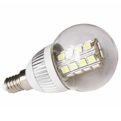
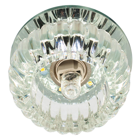
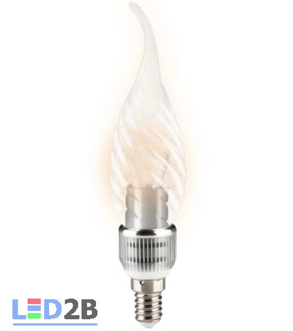
Repair of LED lamp series "LLC" E14 3W1 M1
This lamp is similar to an incandescent lamp. The first thing you notice is the wide metal ring.
I started to disassemble the lamp. The first step was to remove the plafond. As it turned out, it was set on the base with an elastic compound. After I took it off, I realized that it was in vain.
The lamp contained 1 LED, the power of which was 3.3 W. It could be checked from the side of the base.
LED lamps are increasingly being used in everyday life. They are used for lighting and illumination, highlighting the details of the interior. Of particular importance is the circuit of the 220 V LED lamp, specifications which is significantly superior to other types of light sources.
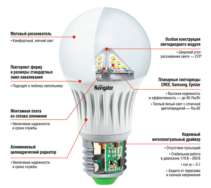
LED lamp elements
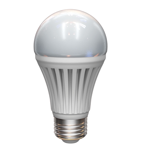
A standard LED lamp contains the following items:
- The main external parts are the diffuser and the base.
- LEDs installed on the board. The whole structure is called. cluster.
- Radiator.
- LED power supply - driver.
Most lamps use standard E27 sockets. Its attachment to the body is carried out by dotted indentations applied along the circumference. To remove the base, the places of the recesses are drilled out or sawn with a hacksaw.
A red wire is connected to the central contact of the base. The black wire is soldered to the thread. Both conductors are very short in length and in case of possible repair of the lamp, you need to have a headroom for extension. After removing the base, a hole opens in the diffuser through which the driver is clearly visible. It is attached to the body with silicone, and it can only be removed through the diffuser.
The cluster, which is an LED board, is powered by a driver. Under its action, there is a transformation alternating voltage 220 volts d.C.... The drivers have parameters such as output current and power.
Thus, the interaction of all elements ensures the stable and trouble-free operation of the entire lamp. Failure of at least one of them will cause failure of the entire system.
LED power supply circuits
The simplest circuit is made using a resistor that acts as an LED current limiter. The normal operation of the circuit in this case depends only on the correct choice of the resistance of this resistor. This food is mainly used when you need to do lED backlight in the switch.
More complex schemes are performed using diode bridge... From its output, a rectified voltage is supplied to the LEDs connected in series. Smoothing of rectified voltage ripples is carried out using an electrolytic diode bridge installed at the output.
The main advantages of both schemes are their low cost, small size and rather simple repair. However, they have a very low coefficient useful action and a high ripple factor.
Perfect power supplies - drivers
The newest LED lamps are equipped with drivers based on a pulse converter. They have high efficiency and minimal ripple. However, their cost is much higher than the simple options already considered.
Silicone paste is used to attach the driver to the case. To gain access to this element, the diffuser is first sawed off, and then the LED board is removed. Power supply for 220 volts occurs using red and black wires from the lamp base. Power is supplied to the LED board by colorless wires.
The driver can work stably at mains voltage drops from 85 to 265 volts. In addition, the circuit of a 220 V LED lamp provides protection against short circuits, as well as the presence of electrolytic capacitors that ensure operation when high temperature, up to 105 degrees.
For the manufacture of lamp bodies, aluminum and special plastic are used, which dissipate heat well. Thanks to high-quality heat dissipation, the service life of the main elements of the lamp increases to 40 thousand hours. More powerful lamps are equipped with heat sinks attached to the LED board with a layer of thermal paste.
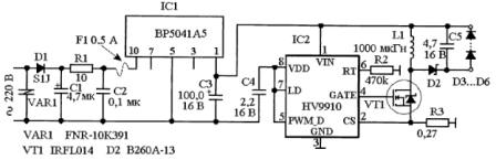
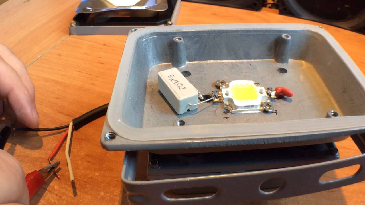
Today in the article we will consider a diagram of how to transfer energy saving light bulb under an LED lamp powered by a 220 Volt network.
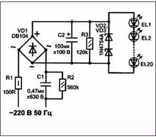
So, after disassembling and removing a completely workable converter from it, the details of which will still serve us for further designs - take at least excellent high-voltage transistors MJE13003,13001; symmetrical dynistor DB3 for the power regulator, or diodes IN4007 (700V 1A), we have a good case with a base and six holes for ... of course, large LEDs Ф10mm. It is them, and not the standard 5mm, that I recommend for use in LED lamps, flashlights, etc. At a slightly higher price (0.5ue) than that of conventional LEDs, they give a much higher brightness at the same supply current - about 20mA.
All elements of the LED lamp are mounted on a circle made of double-sided foil-coated fiberglass. On the one hand, we cut out sections with a cutter for soldering a chain of LEDs, and on the other hand, for elements of a transformerless power source 18V 25mA. This is exactly how much this LED lamp requires.
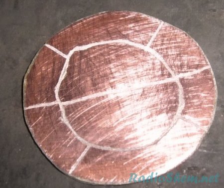
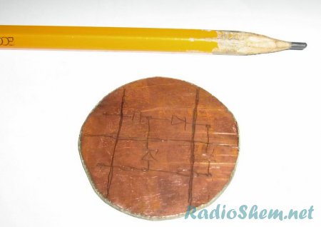
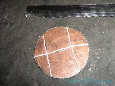
It's easier and faster not to etch the PCB, but to cut the tracks with a cutter made from a hacksaw blade. I did just that, since you also need to spend time etching it. Let's do as soon as possible.
To obtain the required supply voltage for the LEDs, you can use two options for the rectifier circuits:
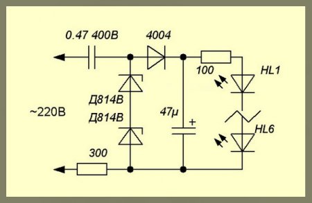
On this one, which is simpler, saving three diodes, we lose almost twice in current. And to compensate, you will have to increase the capacitance from 0.47 to 1 μF. Therefore, I made a choice in favor of such a transformerless rectifier:
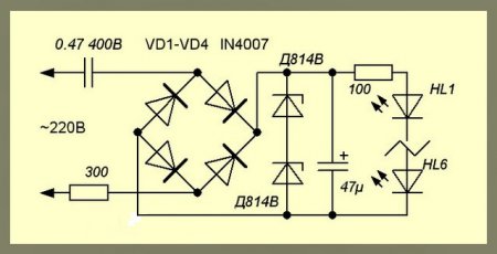
Here, a 300 ohm resistor protects against current surges and at the same time acts as a fuse. We take its power 0.25 watts. Two D814V zener diodes are connected in series and form one zener diode for a voltage of about 20V. If you have a ready-made 19-25V - forward, you can put it alone. The 47μF capacitor smooths out flickering and creates additional protection for LEDs from impulse current surges when the lamp is turned on. With a 100 Ohm resistor, we finally set total current through a line of homemade LED home lamps.
We fix a round scarf with hot melt glue, close the lid so that the LEDs protrude from it halfway, and that's it - the homemade LED lamp is ready. Of course, it cannot compete in brightness with CFL. But in terms of its efficiency, it will give an economical energy saving device - like Belka Strelka. With a power consumption of 18V x 0.025A \u003d 0.4 watts per hour, even if it is never turned off at all, it will consume only 0.4 x 24 x 365 \u003d 4 kW of energy in a year. It is worth it at the level of one passage in public transport. Therefore, if you need constant illumination of the corridor, workplace, utility room on duty, etc., this will be ideal.
Several years ago 4 LED bulbs model GL5.5-E27 were purchased under the Estares brand. Two of them worked well in the hallway, where the lighting is on for several hours a day with periodic switching, one in the bathroom and another one in the toilet, where the operating mode is characterized by more frequent switching than the duration of operation.
But, despite the difference in operating conditions, after three years, all the bulbs began to blink almost simultaneously a few minutes after turning on.
The reason for this phenomenon is known - LEDs gradually fail due to the increased current flowing through them. The manufacturer, to make the lamp shine brighter, uses a driver with the maximum output current for this type of LED. As a result, the LEDs during operation heat up above the permissible temperature for this type of LEDs, and, accordingly, degrade faster. In this case, the brightness of the lamp glow over time begins to decrease, this is visible with the naked eye. The resistance of the LEDs also decreases and reaches the limit at which the protection of the driver against overload and short circuit begins to work, this causes the light to flash.
For the sake of interest and for the sake of economy, it was decided to try to repair these LED lamps, namely to replace the degraded LEDs with new ones and see what happens.
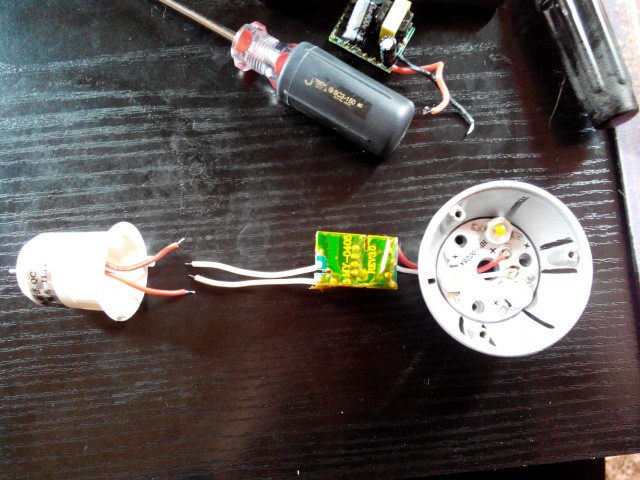
Disassembly of the LED lamp
With an ordinary office knife with a narrow blade, we very carefully cut the glue that attaches the glass lamp cover to the plastic case. We do not press down the plafond, it is very fragile and breaks easily. After cutting the glue, the cover can be easily removed.
It is better to remove all the glue, and there is a lot of it, from both parts of the disassembled LED lamp. We won't need it.
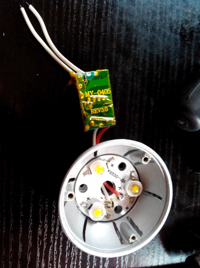
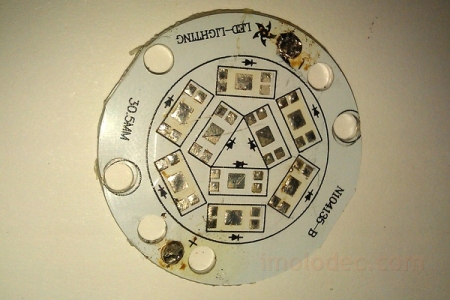
What we see. The thin board has six LEDs, although three more are possible. Obviously, we are dealing with the already classic connection of LEDs to the driver, the same is used in LED strips, three consecutive LEDs. That is, it is possible to install only 9 LEDs in this lamp, three groups of three LEDs each. This will reduce the load on the LEDs and extend the life of the LED lamp.
The board is pressed with self-tapping screws to the plastic case, which has ventilation holes, through an aluminum heatsink.
We unsolder the wires from the board and disassemble this layer cake. There is no thermal paste between the board and the heatsink. The question is whether it is needed there rhetorical.
We find the driver board under the radiator. Note the discoloration of the red positive lead. This is clearly caused by the increased temperature.
Observe the rules of electrical safety!
Lyrically-theoretical digression
But if there is a great desire to see what is there and how, then carefully pry the lamp base around the perimeter with a screwdriver and twist the base along the thread. We pry on the end contact and take it out. The driver board is then freely removed.
In the photo, there is no wire going to the end contact.
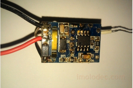
As you can see, the manufacturer was not original and used a typical LED lamp driver on the BP3122 microcircuit. ...
A typical BP3122 application is as follows:
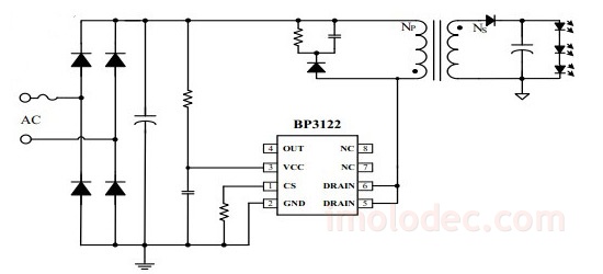
This IC was specially designed for use in LED lamp drivers and is a switching power supply control IC. Its use can significantly reduce the size of the driver, and as a result, and its cost, by reducing the use of additional components.
The output power recommended by the microcircuit manufacturer is no more than 6 W at an input voltage of 230 V ± 15% and 5 W in the range of AC input voltages from 85 to 265 V. The microcircuit implements overload and short circuit protection, overheating protection, and protection against overvoltage. With self-return mechanism when troubleshooting.
The level of the stabilized output current is determined by the type of transformer used, namely, the ratio of turns of the primary Np and secondary Ns windings, and the peak current in the MOSFET, which in turn depends on the resistance of the driving resistor connected to the CS input of the microcircuit.
Current stabilization at the output of the investigated driver is carried out at 350 mA.
LED lamp repair
To replace the degraded ones, new LEDs were ordered from this seller on AliExpress.
The easiest way to unsolder the old LEDs from the board is by means of a hair dryer, a soldering station (temperature about 300 ° C). You can also use a soldering iron, but you have to tinker with making a special "fork for soldering LEDs". The board is very heat-consuming and takes some of the heat onto itself, so a soldering iron less than 100 W can even be ignored.
Removing the old LEDs, without stopping the heating from the bottom of the board, apply flux to the soldering points, solder if necessary, and place new LEDs, observing the polarity.
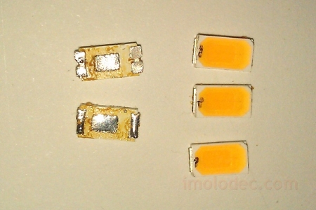
Previously, the conclusions of the new LEDs also do not hurt to tin. And for the convenience of their subsequent positioning on the board, mark, for example, the anode, with a marker.
The nominal data of the purchased LEDs: current 150 mA, voltage 3.0 - 3.2 V, warm white glow 2800 - 3500 K.
Assembly is carried out upside-down. If there is thermal paste, apply it to the back of the board.
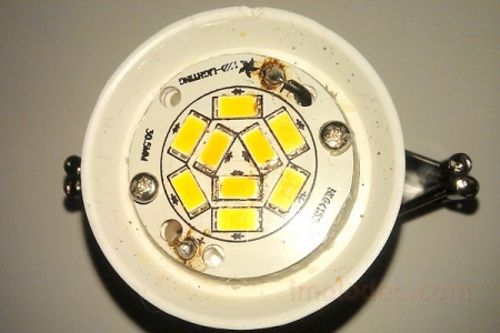
After that, the performance of the LED lamp can be checked by turning it on for several hours.
Do not look at the burning LEDs with an unprotected eye, it is dangerous for your eyes. Cover them with a piece of paper!
If everything is normal, all groups of LEDs light up evenly and do not blink, you can glue the glass cover in place. It is better to use Moment type glue for this. Hot melt glue is not suitable, when the lamp heats up during operation, it can melt and the cover will come off and fall.
After the glue dries, the LED lamp will serve you faithfully again. Well, if suddenly that, you already know how to fix it.