What is a circuit diagram. DC electrical circuit and its characteristics
Electric circuit is a set of devices designed to generate, transmit, convert and use electrical energy, processes in which can be described using the concepts of electric current, voltage and emf
Electrical circuits (2.2) also include switching and protective equipment. Electrical circuits may include electrical instruments for measuring current, voltage and power.
When describing electrical circuits, the following concepts are used: branch of an electrical circuit, node of an electrical circuit, circuit, two-terminal network, four-terminal network.
Branch of the electrical circuit- this is a section whose elements are connected in series. The current in all elements is the same.
Electrical circuit assembly- this is the connection point of three or more branches of the electrical circuit (2.3).
Circuit is any path along the branches of an electrical circuit that begins and ends at the same point.
Two-terminal network- this is part of an electrical circuit with two dedicated terminals.
Quadrupole- part of an electrical circuit with two pairs of terminals.
Operating modes of electrical circuits
The electrical circuit, depending on the value of the load resistance R, can operate in various characteristic modes:
nominal;
agreed;
idle;
Nominal mode- this is a design mode in which circuit elements (sources, receivers, power lines) operate under conditions corresponding to design data and parameters.
The insulation of the source, power line, and receivers is designed for a certain voltage, called the rated voltage. Exceeding this voltage leads to insulation breakdown, increased current in the circuit and other emergency consequences.
The thermal regime of energy sources or receivers is designed to release a certain amount of heat in them, that is, for a certain power, and the latter depends on the square of the current R.I. 2 , rI 2 .
The thermal current calculated is called the rated current.
The rated power value for an electrical energy source is the maximum power that the source normal conditions work can be transferred to an external circuit without the danger of breakdown of insulation and exceeding the permissible heating temperature.
For electrical energy receivers such as motors, this is the power that can be developed on the shaft under normal operating conditions. For other receivers of electrical energy (heating and lighting fixtures) is their power at nominal mode. Rated values of voltages, currents and powers are indicated in product data sheets.
Harmonized operating mode- this is the mode in which the electrical circuit (source and receiver) operates when the load resistance R is equal to the internal resistance of the source r. This mode is characterized by the transfer of the maximum possible power from a given source to the receiver. However, in a matched mode, the efficiency = 0.5 is low and for high-power circuits, operation in a matched mode is not economically profitable. Matched mode is used mainly in low-power circuits if the efficiency. is not significant, but it is necessary to obtain as much power as possible in the receiver.
No-load and short circuit mode. These modes are the limiting modes of operation of the electrical circuit.
In idle mode, the external circuit is open and the current is zero. Since the current is zero, the voltage drop across the internal resistance of the source is also zero (rI = 0) and the voltage at the source terminals is equal to the emf ( = U). From these relationships follows the method of measuring the EMF (2.7) of the source: with the external circuit open, a voltmeter whose resistance can be considered infinitely large is used to measure the voltage at its terminals.
In short circuit mode, the source terminals are connected to each other, for example, the load resistance is closed by a conductor with zero resistance. The voltage at the receiver is zero.
The resistance of the entire circuit is equal to the internal resistance of the source, and the short circuit current in the circuit is equal to:
I short circuit = /r.
It reaches the maximum possible value for a given source and can cause overheating of the source and even damage it. To protect sources of electrical energy and supply circuits from short circuit currents, fuses are installed in low-power circuits, circuit breakers are installed in more powerful circuits, and special high-voltage circuit breakers are installed in high-voltage circuits.
Real electrical circuit - a set of devices designed for transmission, distribution and conversion of energy. Contains sources of electrical energy, receivers of electrical energy, measuring instruments, switching equipment, connecting lines and wires. Electric circuit is a set of consumers (or active and passive elements, respectively) and electrical energy converters connected in a certain way. The chain is called passive, if it consists only of passive elements, and active, if it also contains active elements.Source of electrical energy called an element of an electrical circuit that converts non-electric energy into electrical energy. Consumer of electrical energy called an element of an electrical circuit that converts electrical energy into non-electrical energy. Electrical energy converter called a device that changes the magnitude and form of electrical energy.
In order to perform the calculation, each electrical device must be represented equivalent circuit. The equivalent circuit of an electrical circuit consists of a set of idealized elements (resistor, capacitor, inductor).
Voltage :
The relationship between current and voltage across a circuit element is called current-voltage characteristic (volt-ampere characteristic) element, which is usually represented graphically.
As a consumer in electrical circuit theory DC acts as a resistor characterized by resistance (R), for which Ohm’s law is valid:
Idealized current source- this is a circuit element whose current does not depend on voltage and is a given constant value.
In a real current source, as the voltage increases, the generated current decreases. Any real current source can be reduced to an idealized one as follows:
Combining these two formulas, we get:
For counter current source
The combined form of the generalized Ohm's law for branches containing a current source:
Where the top sign corresponds to the diagram on which U J and J co-directed.
Electric circuit structure.
Branch An electrical circuit is a section whose elements are connected in series one after another and flow around the same current.
Knot An electrical circuit is called the junction of several branches. A node connects at least three branches and is a branching point.
The branches are considered connected sequentially, if they flow around the same current. The branches are considered connected parallel, if they are attached to the same pair of nodes.
Outline An electrical circuit is a collection of branches following one another. The nodes where these branches connect are branching points. When walking around closed the contour's starting and ending points coincide.
A chain in which there are no branches is called single-circuit, in the presence of branches - multi-circuit. A multi-circuit circuit is characterized by the number of independent circuits. A set of independent circuits is determined by the fact that each of the subsequent circuits, starting from the elementary one, is distinguished by at least one new branch. The number of independent circuits can be determined by Euler's formula:
At parallel connection, the role of equivalent conductivity (or conductivity of an equivalent consumer) is played by the sum of the conductivities of all consumers (Fig. 1.12.).
9-10) Equivalent “Star-Triangle” transformation
In nodes a, b, c both the triangle and the star in Fig. 1.14. connect to the rest of the circuit. The transformation of a triangle into a star must be such that when identical values potentials of the points of the same name in the triangle and the star, the currents flowing to these points were the same, then all external circuit“will not notice” the replacement made.
Let's express U ab of the triangle through the parameters of consumers and the currents flowing to these nodes. Let us write down the Kirchhoff equations for the contour and nodes a and b.
Let us replace the currents in the first equation I 3 and I 2 to the corresponding expressions:
Now we get an expression for the same voltage when connecting consumers with a star:
Thus , The resistance of the star beam is equal to the product of the resistances of the adjacent sides of the triangle divided by the sum of the resistances of the three sides of the triangle.
The inverse transformation formulas can be derived independently, or as a consequence of the relations through the conductivities:
Or through resistances:
11) Power balance.
According to the Joule-Lenz law, all electrical energy imparted to a conductor as a result of the work of forces electric field, is converted into thermal energy:
According to the generalized Ohm's law.
This implies the law of conservation of energy, according to which the algebraic sum of the powers supplied to all branches of a branched electrical circuit is equal to zero:
There is another form of recording the power balance:
The left side summarizes the power of energy sources, and the right side sums up the power converted into heat by consumers. Powers that supply energy are taken with a “+” sign, and those operating in consumer mode are taken with a “–” sign.
12) Calculation of unbranched electrical circuits
The basis for the calculation of single-circuit (unbranched) electrical circuits containing sources of both types and consumers is the previously discussed Ohm and Kirchhoff laws.
If there is no current sources, and consumer parameters ( R) and voltage sources ( E) are given, the task is usually to determine the loop current. The positive direction of the desired current is chosen arbitrarily and the equation is drawn up:
If in a circuit other than the consumer ( R) and EMF sources ( E), there is a current source ( J), then the task usually comes down to determining the voltage at the current source U J, because loop current I coincides with the specified source current J. Positive polarity U J is chosen arbitrarily, but it is preferable to put a “+” sign at the tip of the arrow (the formula corresponds to this polarity: ). True polarity U J coincides with the selected one, if during calculation U J is expressed as a positive number, and is opposite to the chosen one if U J. The required voltage drop across the current source U J in the absence of EMF sources is determined by the formula.
13) Method of proportional quantities.
In the branch furthest from the source ( R 6) are specified by a certain value of current or voltage. For ease of calculation, this is usually 1A or 1B. Then, moving to the beginning of the circuit, the currents and voltages of all branches are determined in turn, up to the branch containing the source. This determines which voltage U input and current I V X. must have a source in order to cause in all branches the currents and voltages of the calculated values. If EMF ( E) or driving current ( J) do not coincide with these values, then it is necessary to proportionally change the calculated values of the currents and voltages of the branches by multiplying them by the ratio or .
I 3 can be determined by Kirchhoff's first law:
U 24 is determined by Kirchhoff’s II law:
14) Method of equivalent transformations. Formula for currents in parallel branches.
A branched circuit with a single source is usually simplified by converting it into an unbranched circuit.
Further calculation: .
Current I 3 determined by Kirchhoff's law:
Convenient to use for calculations formula about currents in two parallel passive branches. Let's show it using an example diagram. Voltage according to Ohm's law is determined by the formula
15) Method of Kirchhoff equations.
Designate the branch currents and arbitrarily choose their positive direction.
Randomly select a reference node and set p = m – n + 1 independent circuits.
For all nodes except the reference one, compose equations according to Kirchhoff’s first law. There should be such equations ( n – 1).
For each selected contour, compose equations according to Kirchhoff’s II law. There should be such equations p.
System m Kirchhoff equations with m unknown currents is solved jointly and the numerical values of the currents are determined.
If necessary, calculate the voltage of the branches or the potential difference of the nodes using the generalized Ohm's law.
Check the correctness of the calculation using the power balance.
16) Loop Current Method
The loop currents are taken as the required ones. The number of unknowns in this method is equal to the number of equations that would need to be compiled for the scheme according to Kirchhoff’s II law, i.e. . Based on Kirchhoff's II law
Based on the found loop currents, the branch currents are determined using Kirchhoff's first law.
Thus, the method for calculating a DC circuit using the loop current method is as follows:
Randomly select a set p independent circuits, mark on the diagram the positive direction of the circuit currents flowing in the selected circuits.
Determine your own, total resistance and loop EMF and substitute them into a system of equations of the form.
Self-resistance of the circuit (R ii ) is the arithmetic sum of the resistances of all consumers located in i-th circuit.
Loop EMF represent the algebraic sum of the emf of the sources included in the circuit. With the “+” sign, this amount includes the EMF of sources acting in accordance with the bypass of the circuit; with the “–” sign, this amount includes the EMF of sources acting counter-acting.
Solve the resulting system of equations for loop currents using Cramer's method.
Determine the branch currents through the loop currents according to Kirchhoff’s first law.
Check the correctness of the calculations using the power balance.
17) Method of nodal potentials.
In the case when p- 1– number of nodes, p– number of independent circuits), this method is more economical than the circuit current method. Derived from Kirchhoff's first law and the generalized Ohm's law (through potentials).
Intrinsic conductivity of the node (G ii )
is the arithmetic sum of the conductivities of all branches connected in i-th node.
Designate all branch currents and their positive direction.
Randomly select a reference node (?
n )
and number all the others ( n- 1)-e nodes.
Determine the own and general conductivities of the nodes, as well as nodal currents, i.e. calculate the coefficients in the system of equations.
Total conductivity of the i-th and j-th nodes (G ij = G ji ) is the sum of the conductivities of the branches connected simultaneously to i- oh and j- omu nodes.
The conductivities of the branches with current sources are assumed to be equal to zero and are not included in the own and general conductivities!
Nodal current (J ii ) consists of two algebraic sums: the first contains the currents of the current sources contained in the branches connected in i - om node; the second is the product of the EMF of the voltage sources and the conductivity of the corresponding branches connected in i - om node. With a “+” sign this amount includes E And J sources, action
Electrical engineering examines the structure and operating principle of basic electrical devices used in everyday life and industry. In order for an electrical device to work, an electrical circuit must be created, the task of which is to transfer electrical energy to this device and provide it with the required operating mode.
An electrical circuit is a set of devices and objects that form a path for electric current, the electromagnetic processes in which can be described using the concepts of electric current, emf ( electromotive force) and electrical voltage.
EMF is a quantity characterizing a source of energy of a non-electrostatic nature in an electrical circuit, necessary to maintain an electric current in it. Emf is numerically equal to the work of moving a unit positive charge along closed circuit. Total emf in a direct current circuit is equal to the potential difference at the ends of an open circuit. In SI it is measured in volts.
« Electric current is the ordered (directed) movement of charged particles - electrons"correct only for electric current in a vacuum, or rather, electric vacuum devices.
An alternative to the classical concept of electric current in a conductor is the dipole atomic model. When exposed to the energy of an electric current source, all dipoles of the atoms of the conductor rotate, oriented with their poles of the same name in one direction, providing instantaneous (at the speed of light) transfer of energy to the opposite end of the conductor.
Then the definition of electric current for conductors will look like this:
“Electric current is the ability of conductor atoms to carry out the transfer of electrical charges through magnetic orientation under the influence of the energy of a source of electric current.”
It is not clear what the carrier is electric charge? After all, dipoles do not move along the conductor, they are only oriented along magnetic field, turning on the spot. And charge is a property material bodies and in turn cannot exist without a carrier.
But in reality there is no energy carrier moving along the conductor! Energy moves in the form of photons - point electromagnetic vibrations having a clear geometric shape and polarization. Since a photon has no mass, it is capable of moving at the speed of light - like a radio signal, since both light and a radio signal are also a stream of photons. At the same time, moving with such enormous speed, in the absence of mass it is capable of abruptly (without inertia) changing its direction. If this movement is entrusted to electrons, then they would “pierce” metals, destroying them at the molecular level, like small space “junk” rotating at cosmic speed in near-Earth orbits, and periodically disabling expensive spacecraft, “piercing” the casing of the devices right through. By the way, in electric vacuum devices, where electrons actually act as energy carriers, this phenomenon is observed.
Electrical voltage (electric potential) is measured by an instrument called a Voltmeter - the potential difference that causes current to flow is measured in Volts (V). Just as for current, to increase the range of designations, there are multiple prefixes: (micro - microvolt (µV), miles - millivolt (mV), kilo - kilovolt (kV), mega - megavolt (MV).
For analysis and calculation, an electrical circuit is graphically represented in the form of an electrical diagram containing symbols of its elements and methods of connecting them. The electrical diagram of the simplest electrical circuit that ensures the operation of lighting equipment is shown in Fig. 1.1.
All devices and objects included in the electrical circuit can be divided into three groups:
1) Sources of electrical energy (power).
Common property All power sources are the conversion of some type of energy into electrical energy. The sources in which the conversion of non-electrical energy into electrical energy occurs are called primary sources. Secondary sources are those sources that have electrical energy at both the input and output (for example, rectifier devices).
2) Consumers of electrical energy.
A common property of all consumers is the conversion of electricity into other types of energy (for example, a heating device). Sometimes consumers call it a load.
3) Auxiliary elements of the circuit: connecting wires, switching equipment, protection equipment, measuring instruments, etc., without which the real circuit does not work.
All elements of the circuit are covered by one electromagnetic process.
IN electrical diagram in Fig. 1.1 electrical energy from an emf source E having internal resistance r 0, with the help of auxiliary elements, the circuits are transmitted through the adjusting rheostat R to consumers (load): light bulbs EL 1 and EL 2.
Basic concepts and definitions for an electrical circuit
For calculation and analysis, a real electrical circuit is represented graphically in the form of a calculated electrical circuit (equivalent circuit). In this diagram, real circuit elements are depicted by symbols, and auxiliary circuit elements are usually not depicted, and if the resistance of the connecting wires is much less than the resistance of other circuit elements, it is not taken into account. The power source is shown as a source of emf E with internal resistance r 0, real consumers of direct current electrical energy are replaced by their electrical parameters: active resistances R 1, R 2,…, R n. Using resistance R, the ability of a real circuit element to irreversibly convert electricity into other types, for example, thermal or radiant, is taken into account.
Under these conditions, the diagram in Fig. 1.1 can be presented in the form of a calculated electrical circuit (Fig. 1.2), in which there is a power source with EMF E and internal resistance r 0, and consumers of electrical energy: control rheostat R, light bulbs EL 1 and EL 2 are replaced by active ones resistances R, R 1 and R 2.
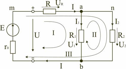
The EMF source in the electrical circuit (Fig. 1.2) can be replaced by a voltage source U, and the conditional positive direction of the voltage U of the source is set opposite to the direction of the EMF.
When calculating, several main elements are distinguished in the electrical circuit diagram.
A branch of an electrical circuit (circuit) is a section of a circuit with the same current. A branch can consist of one or more elements connected in series. Scheme in Fig. 1.2 has three branches: branch bma, which includes elements r 0 , E, R and in which current I arises; branch ab with element R 1 and current I 1; branch anb with element R 2 and current I 2 .
An electrical circuit (circuit) node is a junction of three or more branches. In the diagram in Fig. 1.2 – two nodes a and b. Branches attached to the same pair of nodes are called parallel. Resistances R 1 and R 2 (Fig. 1.2) are in parallel branches.
A circuit is any closed path passing along several branches. In the diagram in Fig. 1.2, three circuits can be distinguished: I – bmab; II – anba; III – manbm, in the diagram the arrow shows the direction of bypassing the circuit.
Conditional positive directions of EMF of power sources, currents in all branches, voltages between nodes and at the terminals of circuit elements must be set to correctly write equations describing processes in an electrical circuit or its elements. In the diagram (Fig. 1.2) we indicate with arrows the positive directions of the EMF, voltages and currents:
a) for EMF sources - arbitrarily, but it should be taken into account that the pole (source terminal) to which the arrow is directed has a higher potential relative to the other pole;
b) for currents in branches containing EMF sources - coinciding with the direction of the EMF; in all other branches arbitrarily;
c) for voltages - coinciding with the direction of the current in a branch or element of the circuit.
All electrical circuits are divided into linear and nonlinear.
An element of an electrical circuit whose parameters (resistance, etc.) do not depend on the current in it is called linear, for example an electric furnace.
A nonlinear element, such as an incandescent lamp, has a resistance, the value of which increases with increasing voltage, and therefore the current supplied to the lamp.
Consequently, in a linear electrical circuit all the elements are linear, and an electrical circuit containing at least one nonlinear element is called nonlinear.
Topic: Electromagnetic phenomena
Lesson: Electric circuit and its components
Let us remember that in the last lesson we stipulated three conditions for the presence of electric current:
1. presence of charges;
2. presence of a current source (galvanic cell, etc.). The current source creates electric field inside the conductor, which causes the movement of charges;
3. presence of an electrical circuit. We will talk about the last concept today.
The electrical circuit must contain a current source (Fig. 1-3), i.e., an element that creates an electric field in the circuit and ensures the movement of charged particles, and a current consumer, i.e., for example, any household appliance (Fig. 4) : light bulb, flashlight, computer, TV, washing machine, refrigerator, etc. The current source and consumers are always connected by wires (conductors), i.e., by elements that are capable of conducting electric current and have a large number free charged particles.
Rice. 1. Galvanic cell ()
Rice. 2. Battery ()
Rice. 3. Power plant ()
 |
 |
|
 |
 |
 |
Thus, the electrical circuit has the following main components: current source, current consumers, connecting wires.
Of course, current consumers themselves consist of smaller elements, each of which has its own name, function and features. Electrical circuits can be complex and simple; we will start studying them with the simplest options, for example, with the device of a flashlight. Its components include: power supply, light bulb, connecting wires and switch. At the end of the lesson, we will assemble an electrical circuit similar to the circuit inside a flashlight and discuss how it works.
For convenience, electrical circuits are usually depicted in the form of diagrams in which certain designations for various elements are adopted. The symbols of the elements of electrical circuits are known and classified in a certain way, there are quite a lot of them, but we will get acquainted with the main ones.
Definition. Electric circuit shown in the figure is called electrical diagram.
|
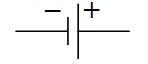
Galvanic cell(current source) As can be seen from the figure, a long strip indicates the positive pole of the source, and a short strip indicates the negative pole |
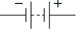
Galvanic battery(battery) This denotes the connection of several galvanic cells |
Connecting wires The place where the wires connect is indicated by a bold dot, which is also often called a node. |
Unconnected wires Wires that do not connect do not stand out particularly at the intersection point |
|
Incandescent lamp(bulb) |
Clamps for connecting electrical appliances You can connect any electrical appliance to a similar element in the diagram |
Key(switch) Circuit element for closing and opening it |
Electric bell To remember this designation, you can notice that it looks like a mushroom |
|
Resistor This circuit element has high resistance |
Heating element |
Fuse A device that ensures the safety of an electrical circuit |

The elements indicated in the table are components simple electrical circuits.
Let's consider the simplest electrical circuit using the example of a flashlight. It includes a power source, an incandescent light bulb, connecting wires and a switch (key).
It is convenient to assemble the circuit in the following sequence: first, connect the light bulb to one of the poles of the current source (battery), then connect the second contact on the light bulb to a previously opened key (switch) and, to close the circuit, connect the second contact of the key to the free pole of the current source.
After collecting the circuit, it is clear that the light bulb does not light up, because it is still open with the key, and no electric current flows (the condition of closing the electrical circuit is not met). Now we close the key, and the light comes on (Fig. 5), because the circuit becomes closed and all conditions for the existence of an electric current are met.
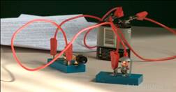
Rice. 5.
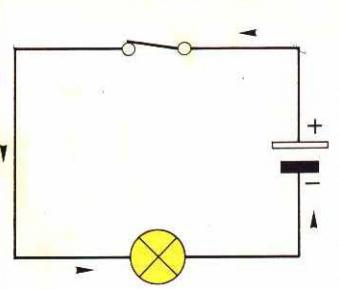
Let us draw a diagram of the electrical circuit we have assembled using the data in the table symbols(Fig. 6).
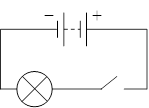
Rice. 6.
Of course, it makes no sense to consider from a practical point of view those electrical circuits in which the work of an electric current is not performed. We will talk about the action of electric current and how it performs work later.
In the next lesson our topic will be “Electric current in metals.”
References
- Gendenshtein L. E., Kaidalov A. B., Kozhevnikov V. B. Physics 8 / Ed. Orlova V. A., Roizena I. I. - M.: Mnemosyne.
- Peryshkin A.V. Physics 8. - M.: Bustard, 2010.
- Fadeeva A. A., Zasov A. V., Kiselev D. F. Physics 8. - M.: Education.
Additional precommended links to Internet resources
- Academician ().
- Internet portal Mukhin.ru ().
- YouTube().
Homework
- Page 78: questions No. 1-4, p. 79: exercise No. 13. Peryshkin A. V. Physics 8. - M.: Bustard, 2010.
- At your disposal is a galvanic cell, a light bulb, two keys and connecting wires. Draw schematic diagram an electrical circuit in which the light comes on only when both keys are turned on.
- Iron nail and cut copper wire stuck into a lemon. Will current flow through the wire that connects the nail and the copper wire?
- Three wires hang from the ceiling where the chandelier is attached, through which current flows after the chandelier is connected. If the chandelier is connected correctly, the two switches work in such a way that one of them turns one lamp on and off, and the other turns the other three. Draw a diagram of the connection of lamps in a chandelier, switches and a current source.
Humanity has long learned to use electrical phenomena nature for its practical purposes for obtaining, using, and converting energy. This action is achieved through the use of certain devices. The pieces of equipment together form a system. Such a system is known as an electrical circuit.
Circuit elements
An electrical circuit contains components such as energy sources, consumers, and the wires connecting them.
There are additional circuit devices, such as switches, current meters and protective devices.
The energy sources in the circuit of such a circuit are batteries, current generators and galvanic cells. They are also called
In the receivers of an electrical circuit, electrical energy is converted into another type of energy. Such equipment includes motors, heaters, lamps, etc.
It is worth noting that the system can be external and internal. They differ in the presence of a receiver. An open chain has it in its composition, and a closed chain only
DC electrical circuit
A current whose value does not change over time is called constant.
The circuit through which such a source of electricity passes has a closed system. These are DC electrical circuits. They are made up of various elements.
To provide a constant source of energy, the system uses capacitors. They are able to accumulate reserves of electrical charges.
The capacitance of a capacitor depends on the size of its metal plates.
The larger they are, the more charge this element of the DC electrical circuit can accumulate. Electrical capacitance is measured in units such as farad (f). In the diagram this element looks like this.
Together with current sources and receivers, these elements form direct current electrical circuits.
Series connection in a circuit
A large number of electrical circuits consist of several current receivers. If these elements are connected to each other in series, then the end of one receiver is connected to the beginning of the other. This serial connection systems. 
The resistance in this electrical circuit is equal to the sum of the resistances of all conductors in the system. They lengthen the paths for the passage of current, which will be the same in individual sections of the system.
The electrical circuit diagram in the classic version contains conductors connected in series and is most clearly described by such a device as an electric garland.
The disadvantage of such a system is the fact that if one conductor fails, the entire system will not work.
Parallel circuit connection
An electrical circuit diagram of a parallel type of connection of elements is a system in which the beginning of the conductors contained in it are connected at one point, and their ends at another. Electric current in such an electrical system has several path options. It is distributed in inverse proportion to the resistance of the energy receivers. 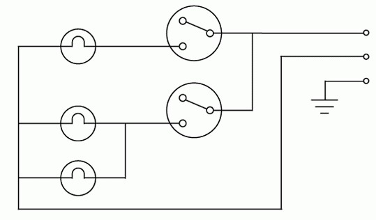
If consumers have the same resistance value, then the same current will pass through them. In the case where one energy receiver has less resistance, it can pass through more current than through other elements of the system.
An electrical circuit and the electric current flowing through it characterize electromagnetic processes using voltage and current. The sum of the individual elements of the system will be equal to the current at the point of their connection.
By connecting new elements to such a circuit, the system resistance will decrease. This is due to an increase in the total cross-section of conductors when connecting a new electricity consumer. A positive characteristic of this method of connecting a circuit is the autonomy of each element.
When one consumer is disconnected, the total cross-section of the conductors decreases, and the resistance of the electrical circuit becomes greater.
Mixed connection in a circuit
The mixed connection option is quite common in the electrical engineering industry. 
This circuit contains both the principle of serial and parallel connection of conductors.
To determine the resistance of several consumers of such a circuit, separately find the resistance of all parallel and series connected conductors. They are equated to a single conductor, which ultimately simplifies the entire circuit.
Circuit operating modes
Based on load indicators, the circuit operates in the following modes: nominal, idle, closed, and matched.
During nominal operation, the system fulfills the characteristics stated in the equipment data sheet. Idling formed in the event of a circuit break. This operating mode is considered emergency. An electrical circuit in short circuit mode has a resistance that is zero. This is also an emergency mode.
Coordination is characterized by movement highest power from the energy source to the conductor. In this mode, the load is equal to the resistance of the power source.
Having become familiar with the basic characteristics and types of a system such as an electrical circuit, it becomes possible to understand the principle of operation of any electrical equipment. This device The operation of the system applies to any electrical household appliance. By applying the knowledge gained, you can understand the cause of equipment failure or evaluate the correctness of its operation in accordance with technical characteristics declared by the manufacturer.