Dielectric mats Tailing term. Dielectric Gloves - Purpose, Application Rules, Testing
Electric Babor Moscow. Testing remedies
1. The leading part
After making the means of protection, it is necessary to subjected to the receiving standards (each sample), periodic and typical tests (GOST 16504-81). When operating, the protection means should be subjected to periodic and extraordinary (performed after repair) tests. The means of protection, in addition to insulating supports, portable earths, fences, posters and signs, obtained for operation from plants - manufacturers or warehouses, must be tested on operating test standards. For sustained tests of protection, except tool with insulating handles and voltage pointers up to 1000 V, it is necessary to put a stamp where the number of protection is specified, up to how many square meters and the date of the next test. On the means of protection recognized as unsuitable, the old stamp must be crossed out with red paint. In a laboratory testing means of protection, record the results of electrical and mechanical tests in the log of arbitrary shape.
This technique shows the description of the following protection tools:
Insulating rods
Insulating and electro-measuring ticks
Voltage pointers above 1000 V with a gas-discharge lamp
Voltage pointers for phasing
Voltage pointers up to 1000 V
Dielectric gloves;
Dielectric shoes (bots, galoshes);
Dielectric caps.
Insulating overlays.
Plumbing tool with insulating handles.
2. Meeting Tests and Measurement Means
For each dielectric means Your test method.
Insulating rods In electrical installations below 110 kV three multiple linear, but not lower than 40 kV, in electrical installations 110 - 500 kV three multiple phase, for 5 minutes 1 time in 24 months.
Measuring rods In electrical installations below 110 kV three multiple linear, but not lower than 40 kV in electrical installations 110 - 500 kV three multiple phase, for 5 minutes 1 time at 12 months.
Insulating and electro-measuring ticks The voltage up to 1000 V is tested with a voltage of 2 kV for 5 minutes 1 time in 24 months .. ticks on a voltage of 6-10 kV and 35 kV are tested with voltage equal to 3-fold linear, but not less than 40 kV and 105 kV respectively in For 5 minutes 1 time in 24 months.
Voltage pointers above 1000 V with a gas-discharge lamp. Insulating part in electrical installations 2 - 35 kV three multiple linear, but not lower than 40 kV in electrical installations 35 - 220 kV three multiple phase, for 5 minutes 1 time in 12 months. Working part In electrical installations 2 - 10 kV are tested by a voltage of 20 kV; 6 - 20 kV are tested with a voltage of 40 kV; 10 - 35 kV are tested with a voltage of 70 kV;, for 1 minute 1 time in 12 months. Ignition tension: In electrical installations 2 - 10 kV are tested with a voltage not higher than 0.55 kV; 6 - 20 kV are tested not higher than 1.5 kV; 10 - 35 kV are tested not higher than 2.5 kV; 35 - 220 kV are not higher than 9 kV voltage;
Voltage pointers above 1000 in contactless type Insulating part in electrical installations 6 - 35 kV are tested with a voltage of 105 kV within 5 minutes 1 time in 12 months.
Voltage pointers up to 1000 V In electrical installations 1 kV ignition tension Not higher than 0.09 square meters. Insulating part and connecting wire in electrical installations up to 0.5 kV are tested with a voltage of 1 kV; In electrical installations up to 0.66 kV are tested with a voltage of 2 kV for 1 minute. Checking the health of the scheme: Single-pole pointers in electrical installations up to 0.66 kV are tested with a voltage of 0.75 kV leakage current no more than 0.6 mA for 1 minute. Two-particular pointers in electrical installations up to 0.5 kV are tested with a voltage of 0.6 kV leakage current no more than 4 mA for 1 minute; In electrical installations up to 0.66 kV are tested with a voltage of 0.75 kV leakage current not more than 4 mA for 1 minute
Voltage pointers for phasing. Insulating part In electrical installations 3 - 10 kV and 6 - 20 kV are tested with a voltage of 40 kV in electrical installations 35 - 110 kV are tested with a voltage of 190 kV, within 5 minutes 1 time in 12 months. Working part In electrical installations 2 - 10 kV are tested by a voltage of 20 kV; In electrical installations 6 - 20 kV are tested with a voltage of 40 kV; In the electrical installations of 35 kV are tested by a voltage of 70 kV, in electrical installations of 110 kV are tested with a voltage of 140 kV; Within 1 minute 1 time in 12 months. Ignition voltage according to the consonant inclusion scheme: In electrical installations 3 - 10 kV are tested with voltage 12 ,.7 kV; In electrical installations 6 - 20 kV are tested with a voltage of 28 kV; In electrical installations of 35 kV are tested with a voltage of 40 kV; 110 kV are tested with a voltage of 100 kV; According to the counter-inclusion scheme: In electrical installations 3 - 10 kV are tested with a voltage of 2.5 kV; In electrical installations 6 - 20 kV are tested with a voltage of 4 kV; In electrical installations of 35 kV are tested by a voltage of 20 kV; 110 kV are tested with a voltage of 50 kV; connecting wire: In electrical installations 3 - 10 kV are tested with a voltage of 20 kV; In electrical installations 6 - 20 kV are tested with a voltage of 20 kV; In electrical installations 35 - 110 kV are tested with a voltage of 30 kV;
Dielectric gloves Tested by increased voltage of 6kV for 1 min., Current through the product should not exceed 6 mA, there should be no sharp fluctuations of the rules of the milliammeter.; 1 time in 6 months.
Dielectric hashi. Tested with a voltage of 3.5 kV for 1 min., Current through the product is not more than 2 mA. 1 time in 12 months
Dielectric bots Tested with a voltage of 15 kV for 1 min., Current through a product not more than 7.5 mA. 1 time in 36 months
Insulating overlays. Hard In electrical installations up to 1 kV are tested by a voltage of 2 kV; For 1 minute electrical installations up to 10 kV are tested with a voltage of 20 kV; In electrical installations of 15 kV are tested by a voltage of 30 kV, in electrical installations up to 20 kV are tested with a voltage of 40 kV; Within 5 minutes 1 time in 24 months. Rubberin electrical installations, up to 1 kV are tested by a voltage of 2 kV, the current through the product should not exceed 6 mA; Within 1 minute 1 time in 24 months.
Plumbing tool with insulating handles In electrical installations of 1 kV are tested by a voltage of 2 kV for 1 minute 1 time in 12 months
For testing tools apply:
|
Name |
Measurement limit |
Accuracy class |
|
Milliammermeter E523. |
5, 10, 20 mA |
|
|
Kilovoltmeter E378 |
0-6 kV. |
|
|
Kilovoltmeter E378 |
0-60 kV. |
|
|
TN I-50 |
0-6 kV. |
|
|
High-voltage installation AII-70 |
~ 0-50 kV. |
3. Security payments
3.1. When assembling the test diagram, a protective and working grounding of the test installation should be performed and, if required, the protective grounding of the body of the test equipment. Before connecting the test installation to the network 380/220 in the output high voltage It must be grounded. The cross section of the copper wire used in testing schemes for grounding must be at least 4 mm.
3.2. To remove grounding that impede the testing, and it is possible to install them again only to indicate the test manager after grounding the output of high voltage test installation.
3.3. It is prohibited from the moment of supplying the voltage to the output of the test unit enter it, touch it to the test installation case.
3.4. After completing the test, the manufacturer of the work should reduce the voltage of the test installation to zero, turn it off from the 380/220 V network and ground the installation output. Only after that you can connect the wires or in the case of a complete end of the test disconnect them from the test installation.
4. Reincarnations to the personnel
Tests of insulating materials using stationary test plants, in which current-carrying parts are closed with solid and mesh fencing, and the doors are equipped with a lock, an employee with a qualifying group according to TB III is solely.
Persons who admitted violations of PTB and PEEP, as well as distorting indications and accuracy of measurements, are responsible in accordance with the legislation and the "Guidelines for the Quality" of the Electrotechnical Laboratory, LLC ESCM Corporation.
5. testing tests
5.1. General provisions
5. 1.1. Before electrical tests, protection means must be subjected to an outdoor inspection to check their size, and certification, completeness, state of insulating surfaces. In case of non-compliance of the tools for the requirements of the requirements of these Rules, the attempts are not carried out before eliminating the detected deficiencies.
5.1.2. All tested, as a rule, should be carried out alternating current 50 Hz frequency at +15¸ +20 ° C.
The speed of voltage lifting up to 1/3 of the test may be arbitrary, further increases the tension to the lodge to be smooth and rapid, but allowing the testing of the measurement instrument at a voltage of more than 1/3. After reaching the desired value, it is strained without excerpt (with a smooth lift) or after shutter speed (for 1 min) it should be quickly reduced, but to a lady and whether the AI \u200b\u200bis valued, equal to 1/3 or mnea test, disabled (GOST 1516.2 -76 ^).
Testing tools of protection from re zein can be carried out permanent (straightened) current.
When testing dC Test tensions should be 2.5 - a multiple of the MU test tensile. The current flowing through the product is not normalized. Continue the test of the test T but as it should be changed.
5.1.3. When tested, an increase in spicy is applied to an insulating part of the means of protection. In the absence of the corresponding source of the voltage required for the insulating means of the princess, the entire method is allowed to test it in a frequent x. At this m, the insulating part of the means of protection deert do not bol well on the Ethe region of the site; A portion of the specified total test voltage, the proportion of the indicated full test voltage, is an ional length and an increased 20 percent.
5.1.4. The main insulating tools of protection, intended for electrical installations with a voltage above 1000 V to 110 kV, the need for IMO test by voltage equal to 3 to a multiple line, but not lower than 40 kV, and the 110 kV anchor can be built for ELA and higher than 3 - Point phase. Additional insulating tools for the shield are tested by voltage, which does not depend on the elah ela, in which they are to refer to Led.
5.1.5. For the yield of the application of complete test voltage is 1 min for isolats AI from porcelain and certain types of non-hygroscopic materials in (for example EP, from fiberglass) and 5 minutes for wasolation from hard-firmed Materia Mater Ialov (for example, from Bakelita). For isolation from rubber when operational tests The duration of the voltage application is 1 min, and when acceptable tests are determined by the technical conditions.
5.1.6. The breakdown, overlapping and discharges on the surface are installed according to the testimony of measuring instruments and the results of the inspections. The currents flowing through the product are normalized for voltage pointers, rubber products and insulating devices for stress work.
5.1.7. Insulating tools from solid organic material immediately after testing should be checked with feeling on the absence of local heating due to dielectric losses.
5.1.8. In the event of a breakdown, overlapping over the surface of surface discharges, with an increase in the leakage current above the normalized value, the presence of local heating from dielectric losses is brazuly.
5.1.9. The norms and frequency of electrical tests are shown in Appendix 5.
5.2. Insulating rods.
5.2.1. When receiving and commissioned and operational tests, the insulating part of the operational and measuring rods is tested by an increased voltage according to clause 3.1.4. In this case, the voltage is applied to the working part and the temporary electrode, superimposed from the restrictive ring from the insulating part. If the isolator is porcelain, the voltage is applied directly to both ends.
5.2.2. When acceptable tests of measuring heads for insulators control are applied voltage 35, with operational 30 square meters.
5.2.3. When receiving and commissioned and operational testing, the rods with the exhausting device are tested with voltage 40 for open contacts for 5 minutes. The test voltage is applied between pantographic capture and contact plate with clip for attaching a grounding conductor. When tested, there should be no overlap on the surface, the breakdown of the air gap between the contacts. If the rods with the exhausting device were in operation, then before operating tests, the exhausting device for stripping the contact part and verify the state of the exhausting material is disassembled.
5.2.4. The grounding rods before each use are inspected for the presence of contaminants, mechanically damage, etc. Isolating part of the composite metal rods for imposing grounding on the wire 330-500 kV wires during receiving and operational tests are tested by a voltage of 100 square meters for 5 min. Norms and deadlines for electrical testing of grounding, which can use as insulating, the same as for insulating rods. Operating electrical tests of the rest of the grounding should not be carried out.
5.2.5. Operational rods The voltage up to 1000 in the receiving and commissioned and operational tests are tested with a voltage of 2 kV for 5 minutes.
5.3. Insulating and electro-measuring ticks
5.3.1. Insulating and electrical metering mites, used electrical installations above 1000 V, are tested according to standards, three-time linear, but not less than 40 square meters for 5 minutes.
5.3.2. Insulating and electrical testers, applied to electrical installations up to 1000 V, are tested by a voltage of 3 kV when receiving and passing and 2 kV under operational testing for 5 minutes.
5.3.3. In insulating ticks, the tension during the test is applied to wire bands at the base of the working part and near the restrictive ring from the insulating part.
5.3.4. When testing electrical inspection ticks, the voltage is applied to the magnetic pipeline and foil electrodes or wire bands for ticks up to 10 kV at the restrictive ring side of the insulating part, up to 1000 V at the base of the handle.
5.4. Voltage pointers above 1000 V with a gas-discharge lamp
5.4.1. Acceptance and operational tests of voltage pointers are in the applied voltage separately to insulating and working parts and in determining the ignition voltage of the pointer. If the working part of the voltage pointers in its design is not subject to elevated; Voltage, test only insulating part and determine the ignition voltage.
5.4.2. When testing the working part of the pointers performed according to paragraph 2.1.31, the voltage is applied to the contact - tip and screw connector. In this case, check the service life of the signal lamp and capacitors. Tests are carried out according to Appendix 5. If the pointer does not have a screw connector connected to electrical scheme Working part, in the boundary of the latter on its surface, the temporary electrode is installed to attach the test installation wire.
The ignition voltage of pointers is determined by the same scheme for which the work part is experienced.
5.4.3. In the voltage indexes of 35-220 kV, the work part is not experienced.
5.4.4. With typical and periodic tests, the indicators with a gas-discharge lamp are tested for the absence of a luminescence from the influence of the adjacent chains of the same voltage, stitched from the pointer to the following distances, mm: in electrical installations with a voltage of up to 6 kV 150, up to 10 kV-220, more than 10 to 35 kV 500, 110 kV - 1500. 150 kV 1800, 220 ê - 2300.
5.5. Voltage pointers above 1000 in contactless type
5.5.1. Reception - the delivery and operational tests of pointers are to check their sensitivity, the directionality of the impact and influence of the press, as well as in testing an insulating rod.
5.5.2. To test the sensitivity, the pointer on the rod is made by the back side to a single wire located under a voltage of 1.5 square meters. The flashing signal should appear when approaching a distance of at least 40-60 mm. To check the focus of the action, the pointer to this wire is made by the side. The distance at which the flashing signal should appear, in which case should be 3 times less than when approaching the back side.
To check the influence of the flooding, the pointer is made by the back side to an ungrounded conductor with a length of 1 m, located and parallel to the conductor, which is located under a voltage of 6 kV from it to a distance of 1 m. In this case, the pointer should not give a signal.
5.5.2. An insulating bar of contactless type pointers and test according to Appendix 5 "Left Application and Testing Tests."
5.6. Voltage pointers for phasing.
5.6.1. Reception - delivery and operational tests of voltage pointers for phasing are in the tests of the pointer in accordance with paragraph 5.5.1. Testing the insulation of the connecting wire, as well as in checking suitability for phase pointer by the scheme of consonant and counter inclusion.
5.6.2. The operating part of the pointer to the voltage of 3-10 kV is tested by a voltage of 20 kV, by 6-20 kV - 40 kV, by 35 kV-70 kV, at 110 kV -140 kV for 1 min. An insulating part should be tested with a voltage of 40 kV for pointers to a voltage of 3-10 kV and 6-20 kV, a voltage of 190 kV-35-110 kV for 5min.
5.6.3. The flexible wire is tested separately with a voltage of 20 kV for pointers to an intense of 3-10 kV and 6-20 kV, a voltage of 30 sq. 35-110 kV for 1 min. The wire is lowered in a water bath with water levels should be 50 mm lower metal tips. One input test transformer It is connected with metallic and tips of the wire, the other is connected to the orpus of the metal bath or electrode, lowered into the water.
Fig.1.
Schematic diagram of voltage pointer for checking the matching phases according to the consonant (s) and oncoming (b) inclusion.
5.6.4. Testing the fitness of the pointer The Wire of the PO with Hem E agreed on and counter-inclination with the goal of this is to check whether the glow of the gas-discharge lamp will not be in the consistent inclusion, and it is installed to be installed on the yenzing voltage at the oncoming inclusion (Table 1).
Table 1.
On the strain of the voltage pointer for phasing
|
N om инан voltage |
N. adjustment Zanigan Iia, KV |
||
|
electrical installations, Kv. |
With consonant inclusion scheme not less |
With a counter-inclusion scheme Not higher |
|
|
3 - 10 |
12,7 |
||
|
6 - 20 |
|||
5.7. Voltage pointers up to 1000 V
5.7.1. Acceptance and operational tests of the tension of the voltage over 1000 in Zack are lucked in testing isolation and [WITH WITH ARE SELL SELL, CHECKING THE SCHEME EXTENSION EMPLICATIONS, DEPENDED AVAILATING ART OF YEARS AND COM EP EN AND COP. flowing through the indication of it, when it is further working voltage to which it is designed.
5.7.2. For tested insulation elevated on a branch in a two-bucket of a Suman pointer, both of the linguing hulls along the entire length right up to the coast of the folly rings are wrapped with foil and the coordinating wire is lowered into a vessel with water so that water closes the entire wire, not reaching the handle by 5-10 mm. One wire from the test installation attach to the contacts - tips, the second, grounded, to the foil and lower it into water (Fig. 2).
In single-pole pointers, an insulating housing over the entire length is wrapped up to a restrictive ring. Between the foil and contact on the head, leave the gap do not pain 10 mm. One wire from the test installation is attached to the contact - tip, second, grounded - to foil.

Fig.2.
Schematic diagram of the test of the electrical strength of the insulation of the handles and wires of the voltage pointer.
For pointers used in electrical installations up to 500, the test voltage is 1 square. In electrical installations of 660 V - 2 square meters. Test duration 1 min.
Insulating part of pocket voltmeters are tested in accordance with the voltage class, and the instrument - according to GOST 8.002 -71
5.7.3. To check the circuit at a two-pole pointer, the voltage from the test unit is applied to the contacts - tips, single-pole pointer - To contact - tip and contact on the head head.
For voltage pointers from gas-discharge lampsapplicable in electrical installations up to 660 V, the test voltage is 750 V, and in electrical installations up to 500 V-600 V. Duration of test 1 min,
5.7.4. The ignition voltage is determined by applying the voltage to the contacts of the tips in two-pole pointers or to the contact - the tip and contact on the body of the case in single-pole.
5.7.5. When testing, the current flowing through the pointer with the highest operating voltage to which it is designed is calculated. This current should not exceed 4 mA for pointers acting in the flow of active current, and 0.6 mA for pointers operating when capacitive current.
5.7.6. With an outdoor inspection of pointers before testing and during operation, the dimensions are checked, the external state of the device is the object of lamps and protective glass, the serviceability of the contacts - the tips and the strength of the connective wire sealing.
5.8. Dielectric gloves, bots and galoshes.
5.8.1. Dielectric gloves, bots and haloshs when receiving and commissioned and operational tests are tested by increased voltage with a current measurement passing through the product.
5.8.2. When testing dielectric gloves, bots and haloshs are immersed in a metal vessel with water having a temperature of +15¸ + 35 ° C, which is also poured inside of these products. Water level both outside and inside the products must be 50 mm below the top edge of gloves, windscreen bot and 20 mm below the galosil sides,
The protruding edges of the test products should be dry. One conclusion of the test transformer is connected to the vessel, the other ground. Inside the product omit electrode connected to grounding through a milliammeter.
Dielectric caps.
5.8.3. Dielectr Favorite caps after making need to be carried out on electrical strength voltage M 10 square meters for 2 min, and in operations Ii -1 every 3 years voltage of 10 kV in for 1 mn and. The method of testing the caps is the same as for dielectric gloves, bot and galleos.
5.9. Insulating stands and dielectric carpets.
5.9.1. In the process of operation, the support and carpets are not subjected to electrical tests. They are rejected during inspections. Carpets should be cleaned of dirt and inspect at least 1 time in 6 months. When defects are detected in the form of punctures, abuse, etc., they should be replaced with new ones. Stands inspect 1 time every 3 years.
5.10. Insulating overlays.
5.10.1. Insulating hard linings made of solid electrical insulating material for electrical installations of 3-10 kV are tested by a voltage of 20 kV, for electrical installations of 15 kV - voltage of 30 kV. For electrical installations 20 kV - voltage of 40 square meters. Test duration 5 min.
5.10.2. To test electrical strength, the lining is first placed between two plate electrodes, the edges of which should not reach the edges of the lining by 50 mm, and then on each side between the electrodes, the distance between which should not exceed the distances between the disconnector poles to the corresponding voltage.
5.10.3. Insulating dielectric rubber overlays for electrical installations up to 1000 V are tested with a voltage of 2 kV for 1 min. The lining with water-swamped with a corrugated surface (in the presence of riflation) is placed between two electrodes, the edges of which should not reach the edges of the lining by 15 mm.
To measure the current flowing through the lining, the transformer supply circuit includes a milliammeter. The current when receiving - delivery tests should not exceed 5 mA, with operational 6 mA. Test duration 1 minute.
5.10.4. Insulating overlays made of solid electrical insulating material to voltage up to 1000 V are experiencing according to the same norms as rubber, but without measuring the leakage current.
5.11. Plumbing tool with insulating handles.
5.11.1. The tool isolation is tested with a voltage of 6 kV when receiving-test tests and 2 kV voltage under operational testing. Test duration 1 minute.
5.11.2. For high voltage testing tool, pre-cleaned dirt and fat, immerse the insulated part in the water bath with water +20¸ 25 ° C, so that the water does not reach the edge of isolation by 10 mm. One test transformer conclusion is attached to the metal part of the instrument, and the second to the bath with water. The second output of the transformer grounds the tests can be carried out on the installation for checking gloves, bot and galleos.
5.12. The procedure for testing the installation of AII - 70.
Feed the test voltage to the products of the test set of AII-70.
5.12.1. Close the door of the compartment where the test is performed - grounding from high-voltage output is automatically removed.
Turn on the plug into the network. In this case, the green "Network" lamp lights up.
5.12.2. Turn on the AV automatic.
Wherein:
The red lamp "VN" lights up.
5.12.3. Press the "Above" button
5.12.4. Voltage lifting is carried out in the latr built into the test installation
Wherein:
Voltage control is carried out by kilovoltmeter. Leakage current control is carried out per milliammeter.
The product is broken if the current passing through it exceeds the norm or there is a sharp fluctuations of the arrow of the milliammeter.
In the event of a breakdown of a defective product, turn off the entire installation.
At the end of the test, the product is dried.
6. Test results
For sustained tests, the means are sewn, except for the tool with insulating handles and voltage pointers of 1000 V, it is necessary to put a stamp that has one of the following forms.
Stamp for electric power supply:
¹____________
suitable until _________
(Laboratory name)
Stamp for protective equipment and safety devices, the use of which does not depend on the voltage of electrical installations (dielectric gloves, gas masks, safety rings, safety ropes, etc.):
¹____________
Date of the next test _______________ 20 ______
_____________________________________________________
(Laboratory name)
The stamp should be knocked out, applied to a sturdy indelible paint or pasted on an insulating part near the restrictive ring of electric power facilities or at the edge of rubber products and safety devices. On the means of sewn consisting of several parts, the stamp put only on one part. On the means of protecting recognized unsuitable, the old stamp should be reproaching red paint.
In a laboratory testing means of protection, record the results of electrical and mechanical tests in the log of arbitrary shape. In the presence of a large amount of funds, the results of their tests can be sewn separately in the log
Dielectric Rubber Protection Test Journal
(gloves, bot, galoshes and insulating linings)
|
name |
inventory |
company |
Tested high voltage, kV |
current flow through |
resoller tati |
date trace. |
Testania |
||
|
remedies |
number |
the owner of the CP-in a row. |
sh. Tok |
permanent Tok |
essay Lie Ma |
test |
test |
provo-Dil |
|
On the means of protection belonging to third-party organizations, also put a stamp and, in addition, the customer is given test protocols
Question 54. Basic and additional electrical equipment up to 1000V. Norms and timing of testing
Electronic protective equipment - means of protection against defeat electric shockdesigned to provide electrical safety.
Insulating electric power facilities are divided into main and extra.
Main insulating electric power facility- Insulating electric power facility, the insulation of which has long been withstanding the operating voltage of the electrical installation and which allows you to work on the current-carrying parts under voltage.
Additional electric power facility- Insulating electric power facility, which in itself cannot, with a given voltage, to protect against electric shock, but complements the main protection means, and also serves to protect against the tap of touch and the step voltage.
Touch voltage- The voltage between the two conductive parts or between the conductive part and the Earth with simultaneously touching the person.
Step voltage- Voltage between two points on the surface of the Earth, at a distance of 1 m one from another, which is taken equal to the length of the person's step.
Main electrical equipment up to 1000V
To the mainstream electroplature in electrical installations with voltage up to 1000V.relate:
Insulating rods of all kinds;
Insulating and electrical testers;
Voltage pointers;
Dielectric gloves;
Manual insulating tool;
Additional electric power plants in electrical installations by voltage up to 1000V include:
Dielectric galoshes;
Dielectric carpets;
Insulating stands and lining;
Insulating caps;
Portable grounding;
Protective fences;
Posters and safety signs.
Tests for testing electric power facilities
Main electrical equipment up to 1000V
|
Name |
Test, kv. |
Periodicity, month |
|
Dielectric gloves |
1 time in 6 months |
|
|
Insulating rods |
1 time in 24 months |
|
|
Insulating pliers |
1 time in 24 months |
|
|
Electric metering |
1 time in 24 months |
|
|
Voltage pointers (500B) |
1 time in 12 months |
|
|
Voltage pointers (660V) |
1 time in 12 months |
|
|
Locksmith-mounted tool with insulating handles |
1 time in 12 months |
Additional electrical equipment up to 1000V
|
Name |
Test, kv. |
Periodicity, month |
|
Dielectric Rugs, Stands |
Periodic inspection |
1 time in 6 months |
|
Insulating lining |
1 time in 24 months |
|
|
Dielectric hashi. |
1 time in 12 months |
|
|
Insulating stairs |
1KV for 1cm. Length |
1 time in 6 months |
|
Portable grounding |
Periodic inspection |
1 time in 3 months and every time after passing over them short circuit currents. |
Periodic inspection- Visually. The person responsible for the presence and preservation of electric power facilities should be 1 time in 6 months. To inspect the record in the journal. For these funds there is no voltage test, only a periodic inspection.
Protective fences, signs and safety posters are not covered.
Dielectric gloves are a protective agent for hand to electricity. The main purpose and the task is to protect the human hands (fingers, palms) from touching the instruments and parts that are under electric voltage. Insulating mittens are the main one. In electrical installation with a voltage of above 1000 V is an additional insulating protective agent from electric shock. In this article, we will consider the appointment, the rules for use and methods of testing dielectric gloves.
Types of gloves
A varieties of such overalls are insignificant. Gloves are manufactured, as a rule, from leaf rubber (rubber) or latex and have one standard size. The width of such workwear should be chosen, taking into account that the warm mittens can be put on them (this is if the work is carried out in cold and frosty weather). If the street is negative, then knitted crags should be put on electrical insulating gloves. This will protect hands from supercooling and charming.
Protective funds are divided into several types:
- bobbin and five plated;
- seamless and seam.
Important! In electrical installations, the use of insulating mittens, which have the mark "EV" and "En" are allowed.
The designation "EV" means that the material is capable of protecting the skin of a person from electricity with a voltage of over 1000 V (of course, as an additional protection method), and the designation "En" - respectively, is considered the main protective coating from the electric flow to 1000 V. This is according to GOST 12.4 .103-83.
Test of strength
The test of electrical insulating gloves is a necessary measure when operating. Conducting such an audit (calibration period) is carried out once every six months (the periodicity of the inspection depends on the mark "EV" and "En").
Scheme checking mittens, bot and gallers for strength:
![]()
- 1 - verification transformer;
- 2 - switch contacts;
- 3 - shunt resistance;
- 4 - gas-discharge lamp;
- 5 – ;
- 6 - ammeter (MA);
- 7 - arrester;
- 8 - Capacity with water.
Before starting the test, the switch from the corresponding contacts is necessary to set to the A. position. This is necessary in order to establish the absence (presence) of the breakdown using the signal lamps. If there is no breakdown, then the switch is moved to the position b and the electric current is measured, which passes through gloves. If the current current exceeds the norm, then such gloves are married. Those mittens that rejected, to use in work is categorically prohibited! Since they are unable to protect a person from electric shock. When the test is completed, the kragi dried.

The inspection scheme may be slightly changed, but the essence remains the same. Now we will look at another test methodology, where we will tell you how to use the installation for checking gloves.
So, the dielectric material of the mittens can be checked by the example: in the tank of the test device and in the sample (gloves) water flows. Its temperature ranges from 10 to 40 degrees Celsius. The distance from the edge of the glove to the water should not exceed 55 millimeters. The edges of the krag and tanks should remain dry.
The voltage that enters the body of the container and the electrode, which goes inside the glove, has its own requirements and equals 6 square meters. Losts one minute test. The milliammeter should show the current value, which passes through the crags - 6 mA.
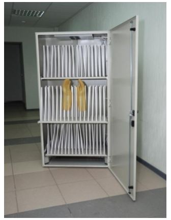
The dielectric material from which mittens is made should dry after testing. To do this, they are placed in a special tank, such as shown in the photo below:
After drying on electrical insulating gloves, you need to put a test stamp on which the date of use of protective crag should be spelled out (the date that the material is suitable). For example:

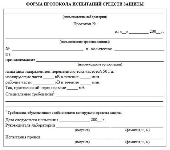
The stamp must be well noticeable, it is necessary to apply it in the indelible paint. Then it is necessary to make information into a log in which the test of protective agents is indicated. The magazine has the following form:

After committing all the above procedures, if there is such a need, a protocol is issued, where it is indicated for the inspection of electrical insulating krag. The sample protocol is as follows:
Terms of Use
The dielectric material from which protective mittens is manufactured has its own service life. Therefore, before putting them into use, it is necessary to check them first. What are the dielectric material check? Special attentiveness should be asked for such moments:
- the presence of an inspection stamp;
- the absence or presence of mechanical damage;
- lack of pollution and moisturizes;
- cracks and other damage.
How to check the products for the presence of cracks and punctures? It is done very simple: you just need to twist the mittens from the edges to the fingers. Thus it will be seen that the dielectric material of Krag has a marriage. In the picture below, the verification methodology is clearly demonstrated:

How can the dielectric material be protected from which protective crags are made from various mechanical damage? To protect it is allowed to wear on top of the mittens of leather or tarpaulin.
At the time of work It is strictly prohibited Wrap the edges of gloves. After each work, you need to wash them using a solution (based on soda or soap). Then they need to carefully dry.
Instructions for the use of krag, which includes dielectric material, standard and it is described on each production before the start of electrical work. Since the purpose of electrically insulating mittens is to protect against electric shock, you should not neglece and need to use products according to instructions and special rules of operation.
Dielectric gloves In electrical installations, the operating voltage up to 1000 V are the main protective agent, and above 1000 V - optional. The main task of this protective agent is to protect a person from directly touching the current parts that are under voltage.
Dielectric gloves are usually made from latex either from sheet rubber, seamless and seamless, respectively. There is a generally accepted standard of glove size - 350 mm. In addition, the width of the gloves should be so that the warm gloves can be put on them (for crawling hands), and the gloves themselves stretch on the sleeves of special clothing.
The use of dielectric gloves
In order to protect yourself from lesion, it is necessary to use dielectric gloves that are suitable for operation. We list the highlights to be paid attention to when checking dielectric gloves:
Purity and lack of moisture on the surface;
Lack of damage;
The date of the next test, that is, the expiration date.
If the surface of the gloves is dirty, they should be thoroughly rinsed with soap solution, and then dry indoors at room temperature.
The absence of visible damage is not a guarantee that the dielectric gloves are suitable for operation, it is possible that there is a puncture that can be visually detected. In order to check the glove on the integrity, it is necessary to twist it down the fingers.
In accordance with the rules of operation of protection tools, dielectric gloves should be periodically testing, so attention should be paid to the date of the next test of the protective agent. For example, today is June 16, and the date of the next test is June 10. Therefore, apply these dielectric gloves is prohibited.
To prevent possible damage to gloves, before starting work on them, gloves from tarpaulin or skin should be applied.
Gloves in operation should periodically undergo disinfection, which is usually as a rule with soda or soap solution.
Test of dielectric gloves
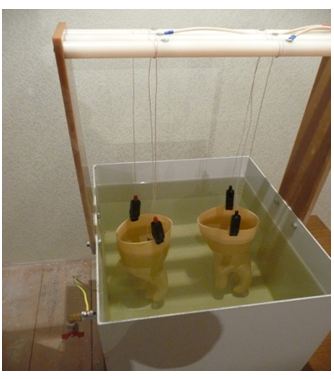
There are generally accepted test standards dielectric gloves, namely once every six months. That is, each time the term of the next test is suitable, this protection means should be handed over to the electrolaboratory, where gloves will be tested in accordance with the norms. Consider the method of testing dielectric gloves.
The metal container is filled with water temperature (the temperature deviation is allowed 10 degrees) and the gloves are placed in the gloves, water is poured into the gloves. In this case, both outside gloves and inside 50 mm remain dry. The test of dielectric gloves is carried out using a special circuit with a test voltage of 6 kV for one minute. The voltage is supplied from the test transformer, one output of which is connected to the Baku and grounds, and the other will be connected to the switch having two positions. First position: Chain transformer-gas-discharge lamp electrode, second position: chain transformer milliammeter-electrode.
The switch is mounted in the first position, the electrodes are lowered directly into the dielectric glove, the voltage is fed. If the lamp lights up, then the breakdown occurred. If there is no breakdown, the switch is set to the second position and the reading of a milliammermeter is monitored, the current on which should not exceed six milliampers.
When the test, with the values \u200b\u200bof the current of more than 6 mA, as well as with unstable readings of the device (oscillation of the arrows), there is a conclusion that the dielectric gloves are not suitable for operation.
After testing, the protective agent is dried at room temperature, the test protocol is written, and a new stamp is pasted on a protective agent, indicating the next test date.
Periodicity of the holding: 1 time per year
Essence of electric measurement:
The insulation resistance measurement is one of the key elements of ensuring fire safety in residential and industrial premises. The measurement of insulation resistance must be carried out during the construction of the building and installation of the power supply system, as well as during the operation of the building.
Damage to the insulating sheath of cables and wires can cause various breakdowns of technology. In addition, damaged isolation may cause fire. To inspect insulation when it has already failed, meaningless. To prevent unpleasant consequences and ensure the maintenance of electrification system, it is recommended to conduct regular insulation resistance measurements.
Basic rules for measuring
- The first measurements are carried out immediately after the manufacture of cables at the manufacturer.
- It is also necessary to check before carrying out installation work, before launching the power supply system. This is done in order to check whether the wires were damaged in the process of carrying out installation work.
- It is very important to measure the measurements before repairing the power supply lines and after the completion of the repair work.
- During the operation of electrical networks, it is very important to periodically produce a prophylactic measurement of the insulation resistance of the cable in order to detect the malfunction of the insulating shell in time and to prevent emergency occurrence in time.
Procedure for measuring work
Measuring work is carried out in the presence of specialized equipment in several stages.
- Visual inspection of wires, cables, transcharges and other electrical equipment. When examined, it is necessary to pay attention to the places where the insulation material was melted. The insulation melting usually occurs due to overheating of the wires and is evidence of the power supply system malfunction.
- Disable wires and cables from electricity sources. It is necessary to disable all the equipment to ensure the safety of the system.
- Directly measurement of insulation resistance is carried out using megommeters - special devices, which are a kind of hommers suitable for working in high-voltage systems.
- Drawing up the documentation in which the state is described electrical networks and make recommendations for troubleshooting.
The insulation resistance is not stable and characterizes its condition at a certain point in time, depending on a number of factors: temperature, insulation humidity at the time of measurement, etc.
The Volt Energo Electric Babor conducts tests of protection tools.
Dielectric gloves - gloves are designed to protect hands from electric shock. Used in electrical installations up to 1000 V as the main insulating electroplature, and in electrical installations above 1000 V - optional. In electrical installations, gloves made of dielectric rubber seamless or with seam, five plated or bobbing can be used.
In electrical installations, it is allowed to use only marking gloves by protective properties of EV and EN. The length of the gloves should be at least 350 mm. The size of the dielectric gloves should allow you to wear knitted gloves to protect your hands from reduced temperatures when working in cold weather. The width along the lower edge of the gloves should allow you to pull them on the sleeves of the outerwear.
Footwear Special dielectric - Special dielectric shoes (galoshes, bots) is an additional electric facility when working in closed, and in the absence of precipitation - in open electrical installations. In addition, dielectric shoes protect the step running from voltage. In electrical installations are used dielectric bots and galoshes made in accordance with the requirements state standards. Galoshs are used in electrical installations with a voltage of up to 1000 V, bots - at all stresses. For protective properties, shoes designate: En - Galoshi, eV - bots. Dielectric shoes should differ in color from the rest of the rubber shoes. Galoshes and bots should consist of rubber vertices, rubber corrugated soles, textile lining and internal amplifying parts. Molded bots can be released by lining. Bots must have challenges. The height of the bot should be at least 160 mm.
The frequency of calibration is 1 time per year.
Dielectric Rubber Carpets - Dielectric Rubber Rubber Rubber and Stands are used as additional electric power plants in electrical installations up to and above 1000 V. Carpets are used in closed electrical installations, except raw rooms, as well as in open electrical installations in dry weather. Stands are used in raw and contaminated areas. Carpets are manufactured in accordance with the requirements of the State Standard, depending on the appointment and conditions of operation of the following two groups: the 1st group - the usual version and the 2nd group - oil-resistant. Carpets are manufactured with a thickness of 6 ± 1 mm, from 500 to 8000 mm long and a width of from 500 to 1200 mm. Carpets must have a corrugated facial surface. Carpets must be monochrome.
Periodicity of verification -in operation, carpets and stands do not experience. They are inspected at least 1 time in 6 months., As well as immediately before use. When mechanical defects are detected, carpets are carried out of operation and replace new, and the stands are sent to repair.
Works are held at any time convenient for the customer!
(Before starting work, it is necessary to notify the contractor about the time of work)
After completing the work, the Customer provides acts of work performed, a technical report, a defective act, the protocols of electrical inspections, the load card.
Our coordinates:
Commercial Director:
Shapovalov A.A., Tel.: 044 209 52 31, 067 506 02 48
Address:
02660, Kiev, ul. Magnitogorskaya, 1a, body 6, housing 12
E-mail:
Site: www.Syt.