Electric motor control system. Electronic engine control units
Controllers for controlling small-sized electric motors
This section presents control devices for small-sized electric motors DC(electric motors with a diameter from 3 to 95 mm, power from 0.001 W to 1100 W), including a power stage, electronics for signal processing feedback, a set of digital and analog inputs and outputs, interfaces for networking using various industrial protocols.
You can familiarize yourself with electronic control units produced by manufacturers of small-sized electric drives for their own and third-party electric motors in the relevant sections (see links): (for brushed, brushless DC motors), Dunkermotoren (for brushed, brushless DC motors), Nanotec (for brushless, stepper motors), Phytron (for stepper motors).
Phytron Modular Controllers for Stepper Motors
The Phytron controller line includes phyMotion™ multi-axis modular controllers (see link). These products are designed to control from 1 to 18 bipolar stepper motors in special conditions - there is support for feedback from temperature sensors for motors located in a vacuum, as well as feedback signals via EnDat, SSI. These controllers operate using one of the common industrial protocols: Ethernet, ProfiBus/ProfiNet, CAN, RS 485, RS 232, RS 422.
You can view the description of all Phytron products at.
DC/BLDC controllers Copley Controls
Microprivod LLC offers control units for brushed, brushless DC motors, as well as stepper motors from Copley Controls with an expanded set of processed feedback signals and higher output powers (operating current up to 30A, peak current up to 60A).
List of feedback signals covered Copley Controls products:
- Relative reference sensors - digital quadrature A/B signal (including with additional output), analog sin/cos signal;
- Absolute encoders - signal in SSI, EnDat, AbsoluteA, SanyoDenkiAbsoluteA, BiSS (B&C) format;
- Resolvers (SKVT);
- Digital Hall sensors.
These controllers allow you to control motors by speed, position, torque, in Camming, Gearing modes, and by index signal.
It is also possible to purchase protected versions of controllers designed to operate in adverse conditions with increased vibration, shock loads and an extended temperature range.
For a description of all Copley Controls products, please visit
The control unit for an asynchronous electric motor is unregulated, non-reversible (BNN).
Unregulated reversible asynchronous electric motor control unit (BNR).
Automatic transfer unit (BAVR).
The blocks are designed to control electric motors with rated current stator up to 100A, at a voltage of 380V AC frequency 50 Hz.
Hardware composition.
The units mainly use domestic equipment:
Automatic switches of types AE1031, AE2036, AE2046, AE2056, BA57-35;
Magnetic starters type PML1100…PML4100, PML1501…PML4500, PM12-100;
Thermal relays type RTL, RTT.
At the customer's request, cabinets can be equipped with equipment from ABB, Schneider, IEK and others.
The control units included in the ShchU-ChE switchboard can be divided into three functional groups:
|
1. Control units for units (pumps, fans, valves). The blocks are designed directly to control the units and contain all the necessary starting protection equipment (circuit breaker, magnetic starter, thermal relay). The block is installed for each unit. These blocks include the BNN, BNR, BRP, BTZ blocks. The BNN, BNR, BTZ units operate autonomously, the BRP unit requires connection to the BPC control unit. The units can control the unit both in local mode (using buttons on the front panel or on an external button station) and in remote (automatic) mode under the control of the automation system of the heating point (the automation system is connected to the terminal block of the control circuits of the unit). The control mode is selected using a switch on the front panel of the unit. Turning on the unit is indicated by a lamp on the front panel. 2. Control unit – BPC unit. This block is designed to regulate the rotation speed of electric motors. The block contains an electronic control device - a frequency converter, power switching equipment and a logical device that controls the operation of the frequency converter and magnetic starters, as well as monitoring the health of the converter. 3. Auxiliary blocks. These blocks include the AVR block. It is usually installed in a ShCH cabinet, one unit for the entire heating unit. Provides power to the heating point automation system, electric fire damper, and emergency lighting circuits. |
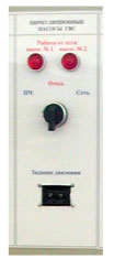
Front panel of blocks BPP, BRP, BTZ
Front panel of the BPCH2 unit (for 2 pumps) |
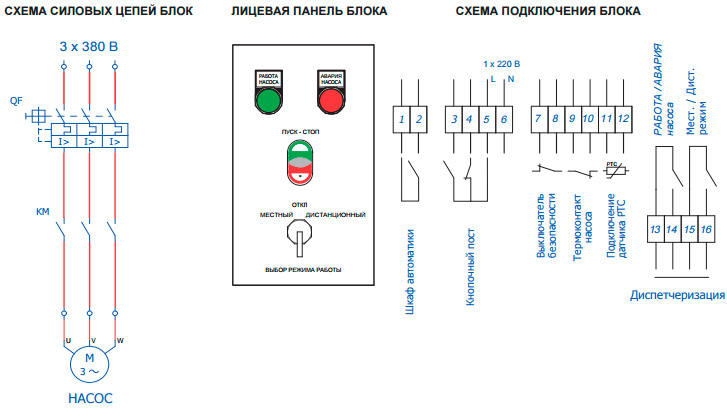
Control unit for asynchronous electric motor, unregulated, irreversible (BNN) designed to control mechanisms with irreversible asynchronous electric motors(pumps, fans, etc.). The unit provides protection of the electric motor circuits from short circuits (using a circuit breaker) and protection from overcurrent (using thermal relay). The unit provides control of the electric motor in two modes – local and remote. In local mode, control is carried out from the buttons on the switchboard door, in remote mode - from the central heating automation system.
Power circuit block circuits |
The mode selection switch has a contact that informs the central heating automation system about the selection of the remote control mode. The block diagram provides for the connection of a safety switch installed next to the controlled electric motor. | |
 |
 Connection diagram for the unit for working with the Tekon device |
|
Unregulated reversible asynchronous electric motor control unit (BNR) designed to control mechanisms with reversible asynchronous electric motors (electric valves, control valves, etc.). The unit provides protection of electric motor circuits from short circuits (using a circuit breaker) and protection from overcurrent (using a thermal relay). The unit provides control of the electric motor in two modes - local and remote. In local mode, control is carried out from buttons installed next to the controlled mechanism, in remote mode - from the central heating center automation system. The block diagram provides the ability to connect limit switches that turn off the electric motor when the mechanism reaches its final positions. The block diagram provides for the connection of a safety switch installed next to the controlled electric motor.
Variable frequency drive control unit (VFD) designed to control non-reversible asynchronous electric motors (pumps, fans, etc.) with the ability to regulate the rotation speed of the controlled electric motor. The block is designed to work together with a frequency converter control unit (FCU). The unit provides protection of the electric motor circuits from short circuits (using a circuit breaker) and protection from overcurrent (using a thermal relay), as well as protection of the frequency converter power circuits (using a circuit breaker). The unit provides control of the electric motor in two modes - local and remote. In local mode, control is carried out from the buttons on the switchboard door (it is possible to turn on the pump in regulated and unregulated mode), in remote mode - from the central heating station automation system. The mode selection switch has a contact that informs the central heating automation system about the selection of the remote control mode. The block diagram provides for the connection of a safety switch installed next to the controlled electric motor.
Frequency converter control unit (FCU) designed to regulate the rotation speed of an asynchronous electric motor by changing the magnitude and frequency of the voltage supplied to the electric motor. The unit is installed alone on a group of pumping units (CW, DHW or CNO) and works in conjunction with variable-frequency electric drive (VFD) control units. The block provides regulation of the electric motor frequency depending on the pressure at the outlet of a group of pumping units (hot water supply, hot water supply) or the pressure drop across the pumping unit (PSU). The required pressure (difference) is set using a digital-analog controller installed on the switchboard door. The block circuit provides the ability to switch the electric motor to an unregulated mode if the frequency converter malfunctions. The activation of the pump in unregulated mode is indicated by a lamp on the switchboard door.
 Power circuit diagram block BPCH2 (for 2 pumps) |
 Block connection diagram BPCh2 (for 2 pumps) |
 BPCH3 (for 3 pumps) |
 Connection diagram for block BPCH3 (for 3 pumps) |
For cold water, hot water, fire pumps, etc. one pressure sensor is installed per group. It is connected to terminals 21(+), 22(-) of the BPC2 block, 31(+), 32(-) of the BPC3 block.
For central heating pumps, two pressure sensors are installed - at the inlet and outlet of a group of pumping units. The sensor at the pump output is connected to terminals 21(+), 22(-) of the BPC2 block, 31(+), 32(-) of the BPC3 block, the sensor at the pump input is connected to terminals 23 (+), 24(-) of the BPC2 block, 33(+), 34(-) BPC3 blocks.
Control unit for an asynchronous electric motor with engine starting using the star-delta method (BTZ).
 Power circuit diagram |
The block is similar to the BNN block, but has an additional magnetic starter that re-switches the electric motor windings from star to delta during acceleration after a specified time delay (1..30 sec). It is used for electric motors designed for voltage 380/660V - for example, at the request of Grundfos, pumps with a power of 5.5 kW or more must be started using the star-delta method. |
|
 |
 |
|
Automatic transfer block (BAVR) designed to automatically switch the load to the backup input in the event of a malfunction (loss of voltage, break of one of the phases, incorrect phase rotation) of the main one. The unit is installed in the ShPCh cabinet, in the RShU-1 and RShU-2 cabinets it is installed circuit breakers, to which the input lines of the block are connected.
BNN and BRP units have additional versions:
BNN-T and BRP-T – a posistor protection module has been added to standard units (an electronic unit that turns off the pump when the temperature sensor built into the motor windings overheats; used with Grundfos pumps).
BNN-P and BRP-P – a device has been added to standard units soft start electric motor (for PDU - in the pump operation circuit from the network).
BNN-PT and BRP-PT - both a posistor protection module and a soft start device have been added to the blocks.
The parameters of the BNN, BRP and BNR control units are given in the table:
| Typical index | Connected motor power, kW | Rated current, A | Thermal relay regulation limits | Circuit breaker | Actuator | Thermal relay |
| 01 | 0,18 | 0,66 | 0,61-1 | AE2036M 1.6A | PML1100 | RTL-1005 |
| 02 | 0,37 | 1,2 | 0,95-1,6 | AE2036M 2A | PML1100 | RTL-1006 |
| 03 | 0,75 | 1,7 | 1,5-2,6 | AE2036M 3.15A | PML1100 | RTL-1007 |
| 03 | 1,5 | 3 | 2,4-4 | AE2036M 4A | PML1100 | RTL-1008 |
| 05 | 2,2 | 5 | 3,8-6 | AE2036M 8A | PML1100 | RTL-1010 |
| 06 | 3,0 | 6 | 5,5-8 | AE2036M 8A | PML1100 | RTL-1012 |
| 07 | 4,0 | 8 | 7-10 | AE2036M 10A | PML1100 | RTL-1014 |
| 08 | 5,5 | 11 | 9,5-14 | AE2036M 16A | PML1100 | RTL-1016 |
| 09 | 7,5 | 15 | 13-19 | AE2036M 20A | PML2100 | RTL-1021 |
| 10 | 11,0 | 21 | 18-25 | AE2046M 31.5A | PML2100 | RTL-1022 |
| 11 | 15,0 | 29 | 23-32 | AE2046M 40A | PML3100 | RTL-2053 |
| 12 | 18,5 | 36 | 30-41 | AE2046M 50A | PML3100 | RTL-2055 |
| 13 | 22,0 | 43 | 38-52 | AE2046M 63A | PML4100 | RTL-2057 |
| 14 | 25,0 | 49 | 47-64 | AE2046M 63A | PML4100 | RTL-2059 |
| 15 | 30,0 | 59 | 54-74 | AE2056MM 80A | PML4100 | RTL-2061 |
| 16 | 37,0 | 73 | 75 | PM 12-100 | RTT-ZP | |
| 17 | 45,0 | 90 | 100 | VA57-35 125A | PM 12-100 | RTT-ZP |
This table shows starting-protective equipment of domestic production.
Control units are a virtual unit for cabinet calculation. The blocks are not delivered separately without a cabinet!
BNN block is a control unit for an unregulated, irreversible asynchronous electric motor. Designed to control mechanisms with irreversible asynchronous electric motors (pumps, fans, etc.). Only one electric motor can be connected to one BNN unit. The block provides protection of electric motor circuits from currents short circuit and overcurrent protection using a motor protection circuit breaker (MPC). The unit provides control of the electric motor in two modes - local and remote. In local mode, control is carried out from the buttons on the cabinet door, in remote mode - from the external automation cabinet. It is possible to connect a safety switch installed next to the controlled electric motor. There are output signals for dispatching the operating mode of the local/remote unit and for dispatching engine operation/emergency.
Table of correspondence between standard sizes of BNN units and current ranges
| Control unit size | Current range, A | Power, kW | Note |
| 01 | 0,63 - 1 | 0,37 | The selection of the unit must be made in accordance with the rated current of the motor, which must be within the specified current range. |
| 02 | 1 – 1,6 | 0,55 | |
| 03 | 1,6 – 2,5 | 0,75 | |
| 04 | 2,5 – 4 | 1,5 | |
| 05 | 4 – 6,3 | 2,2 (3) | |
| 06 | 6 – 10 | 4 | |
| 07 | 9 – 14 | 5,5 | |
| 08 | 13 – 18 | 7,5 | |
| 09 | 17 – 23 | 11 | |
| 10 | 24 – 32 | 15 | |
| 11 | 30 – 42 | 22 | |
Designed for contactless control of electric actuators (EIM) with a single-phase electric motor. The blocks start, reverse, and stop the electric motor in accordance with the discrete input signals “More” and “Less”.
Reversible electric motor control units BUER 3-30-00, BUER 3
Designed for contactless control of electric actuators (EIM) with a three-phase electric motor. The blocks perform starting, reversing, stopping the electric motor in accordance with discrete input signals “More” and “Less”, as well as protecting power switches from short circuits and customizable protection asynchronous motor from overload.
Power supplies BP-G, BP-4M15
Designed to power the controller with an unstabilized direct voltage of 24 V. The units are made according to the traditional circuit using a step-down transformer and are connected to a 220 V alternating voltage network.
Power supply BBP-24
Designed to provide uninterrupted power supply to the controller with an unstabilized direct voltage of 24 V. The unit contains a voltage converter based on a step-down transformer, connected to the network AC voltage 220 V, battery and control circuit, which ensures shock-free switching of connected equipment to a backup power source. The design of the unit uses batteries with a service life of at least 6 years without maintenance.
Block power supply BP-D
Designed to convert unstabilized DC voltage (24±6) V into stabilized DC voltage 17, 22, 24, 36 V (depending on the unit version), and is intended to power sensors used in the construction of automated process control systems with CONTRAST series controllers. The unit is powered from power supplies BP-G, BBP-24, BP-4M15, etc.
Power module MP-D
Designed to power the ShMK microcontroller and USO-D modules. In cases where the power of one MP-D module is not sufficient to power the entire group of USO-D modules installed on the bus, it is possible to connect several MP-D modules to it.
Input block BV-D-50
Designed for use in control circuits for electric drives of pumps and shut-off valves as part of automated process control systems. The block converts the status signals of contact devices into discrete logic level signals.
Power amplifier block BUM-30
Designed to amplify the power of the controller's discrete output signals and contains four relays, each of which has two groups of changeover contacts and is capable of switching 220 V AC electrical circuits.
Block BUM-50
Designed to convert discrete 24 V level signals into relay control signals for power devices.
The block contains 1 relay ( rated voltage winding = 24 V, power consumption 0.8 W) and has one changeover contact. The relay is turned on when DC voltage (=24V) is supplied to the input terminals of the unit.
Switching block BPR-30
Designed to switch the output signal circuits of a redundant controller. The block contains eight low-power relays.
Block BPR-50
Designed for switching signal circuits when redundant controllers, as well as for switching circuits in protection, signaling, and interlocking circuits.
The block contains 5 relays (nominal winding voltage = 24 V, current consumption 8 mA), each of them has two groups of changeover contacts.
Interface converter PI-3
Designed to convert the RS-232C/RS-485 interface.
The converter is used to connect the gateway channel of the controller to the COM port of the computer and maintain stable communication at a distance of up to 1.2 km. The converter is powered by a 220 V alternating voltage network and is installed in close proximity to the computer.
PK-302 controller settings panel
Designed to control operating modes of the controller, operational monitoring and control of technological programs, setting their parameters and parameters of the controller as a whole during operation or preparation for operation
Set of resistors for normalizing SCC
Designed to connect DC signals 0-5 mA, 0(4)-20 mA and DC voltage 0-10 V to the MAU-D module. To connect signals of other types to the MAU-D module, the KRN kit is not required.
Memory protection device
Designed to ensure continuity of DC signal circuits 0-5 mA, 0(4)-20 mA, connected to the corresponding inputs of USO-D modules, when dismantling the modules. The protective device is connected to the modules via an industrial terminal block.
Interface connector IS-485
Designed to organize communication between the USO-D module and a computer through the PI-3 interface converter when programming and configuring the module.
Design and technical requirements
Basic technical data and characteristics
Types of input and output signals, ranges of variation, input resistances are given in Table 2.4.
Table 2.4
|
Type of signal, type of modules |
Signal range |
Note |
|||
|
input |
day off |
||||
|
1 Tension and force are constant |
resistance (50.025) Ohm |
||||
|
MBA-D; MDA-D | |||||
|
MTS-D, MAU-D | |||||
|
2 Signals from the vehicle * MTS-D, MAU-D |
200... +800 o C 200... +1372 o C 50... +1768 o C 0... +2500 o C 0... +1800 o C 0... +1800 o C 50... +1768 o C 200... +1820 o C 210... +1200 o C 200... +400 o C 200... +1000 o C 200... +1300 o C 200... +100 o C | ||||
|
3 Signals from TR * TSP 50P(Pt50) W 100 =1.3910 TSP 100P (Pt100) W 100 =1.3910 TSP 50P(Pt50) W 100 =1.3850 TSP 100P(Pt100) W 100 =1.3850 TSM 50M(Cu50) W 100 =1.4280 TSM 100M(Cu100) W 100 =1.4280 TSM 50M(Cu50) W 100 =1.4260 TSM 100M(Cu100) W 100 =1.4260 TSN 100N(Ni100) W 100 =1.6170 Resistive sensor MRS-D, MAU-D |
200... +750 o C 200... +750 o C 200... +750 o C 200... +750 o C 200... +200 o C 200... +200 o C 50... +200 o C 50... +200 o C 60... +180 o C | ||||
|
4 Digital signal |
Rн 2 kOhm Rн 0.5 kOhm Rн 0.5 kOhm |
||||
|
6 Discrete inputs |
(0-7) V –log. "0" (24±6) V – log. "1" |
Rin 4.8 kOhm |
|||
|
7 Discrete holidays |
“0” - I’ll open it, "1" - closed state transistor switch |
Switching voltage current up to 0.3 A |
|||
|
Note - * Thermocouple (TC) signal ranges according to GOST R 8.585-2001; signals from resistance thermal converters (TR) – according to GOST 6651-94. |
|||||
Dimensions blocks and components controllers and their weight in accordance with table 2.5.
Table 2.5
|
Name |
Overall dimensions, mm |
Weight, kg, no more |
|
Controller unit BK-500 | ||
|
MK-500 with DIN-35 rail mounting MC module modules MC, MR 1, (MR 2) MC with built-in software (MP 1, MP 2) MK-500 with shield mount MC with built-in software MC/PO, MR 1 (MR 2) |
18068(100)x157 188x143x 48.5(79; 111) 188x162x69(101) | |
|
Gateway microcontroller ShMK | ||
|
Reversible electric motor control unit BUER 1-30-00, BUER 3-30-00 BUER 1-30-02; BUER 3-30-02, -03 BUER 1, BUER 3 | ||
|
USO-D dual module | ||
|
Module USO-D single | ||
|
Power module MP-D | ||
|
Power supply BP-D | ||
|
Software operator console | ||
|
Power amplification unit BUM-50 | ||
|
Discrete input block BV-D-50 | ||
|
Switching block BPR-50 |
The controllers are powered from a direct current source with a voltage of (246) V, and with power supplies BP-4M15, BP-G, BBP-24 - variable single-phase current voltage V, frequency (50±1) Hz and higher harmonic coefficient up to 5%.
The power consumed by individual blocks and modules does not exceed the values indicated in Table 2.6.
Table 2.6
|
Blocks and modules |
Power consumption, W, no more |
Note |
|
|
at an output power of 15 W (5V, 3A) |
|||
|
MAS-D, MDA-D single housing | |||
|
MAS-D, MDA-D double body | |||
|
MRS-D, MTS-D, MVA-D, MAU-D single and double body | |||
|
MSD-D single housing | |||
|
MSD-D double body | |||
|
MVS-D single and double housing | |||
Blocks BK-500, ShMK, modules USO-D, MP-D are made in housings made of polymer material and mounted on a DIN rail.
Controllers (BK-500 units) have digital interfaces:
Ethernet network channel;
Master intercontroller network channel - RS-485 interface;
gateway channel for communication with an engineering station or SCADA system - RS-232/RS-485 interface;
channel for communication with the controller panel - RS-485 interface;
redundancy channel - RS-485 interface;
four field network channels - RS-485 interface - for communication with microcontrollers and microprocessor devices both from the KR-500 controller (ShMK, USO-D modules, etc.), and others, specially designed, or from other manufacturers. Each channel has the ability to connect up to 31 field devices. The fourth channel also has the ability to operate in gateway channel mode, communicating with an engineering station or SCADA system.
The ShMK gateway microcontroller has three RS-485 interface channels: two for communication with external objects (BK-500, etc.), one for communication with USO-D modules (up to 16 modules).
The controllers contain a non-volatile timer-calendar.
The analog signal inputs of the IR modules MAS-D, MDA-D are galvanically separated from each other and from other circuits.
The analog signal inputs of the IR modules MVA-D, MAU-D, MTS-D MRS-D are galvanically separated from other circuits.
The outputs of analog signals of the IR modules MAS-D, MAV-D are galvanically separated from each other and from other circuits.
The inputs of discrete channels of the MSD-D-02, MSD-D-03, MSD-04 modules, connected in a group of 4, are galvanically separated from other groups and from other circuits.
The outputs of discrete channels of MDA-D modules, connected in a group of 2, are galvanically separated from other groups and from other circuits.
The outputs of discrete channels of the modules MSD-D-00, MSD-D-01, MSD-D-02, connected in a group of 4, are galvanically separated from other groups and from other circuits.
Modules MAS-D, MDA-D, MAU-D. MVA-D perform diagnostics of analog input channels with an input signal range of (4-20) mA. If the communication line with the sensor is broken, an error signal is generated.
Modules MAS-D, MAV-D perform diagnostics of analog output channels. When the output signal changes by 3% of the specified value, an error signal is generated.
Modules MSD-D-02, MSD-D-03, MSD-D-04 perform diagnostics of communication lines of discrete input channels.
The outputs of discrete channels of the MDA-D, MSD-D-00, MSD-D-01, MSD-D-02 modules are protected against short circuits; the modules perform short circuit diagnostics.
The MDA-D module performs diagnostics for turning the outputs on and off.
If the BK-500 unit fails, a discrete “failure” signal is generated at the output.
After disconnecting from the power supply, the controllers save operational information (current values of the algorithms), and also support the operation of the timer-calendar for at least 24 hours.
When powered by the BBP-24 power supply, the controllers operate for at least 30 minutes after the BBP-24 is disconnected from the power supply ( 220 V, 50 Hz).
The controllers operate in continuous mode.
The operating mode establishment time is 5 minutes, when converting analog signals with a given error of no more than one hour.