Thyristor connection of a three-phase asynchronous motor. Single-phase motor connection: diagrams, check, video.
CALCULATION OF THE CONDENSER FOR A THREE-PHASE ENGINE
V. BASHKATOV, Ukraine, Donetsk region, Gorlovka
Sometimes at home it becomes necessary to connect three-phase electric motor alternating current into a single-phase network.
There was such a need for me when connecting an industrial sewing machine... In a garment factory, such machines work in a workshop with a three-phase network, and there are no problems.
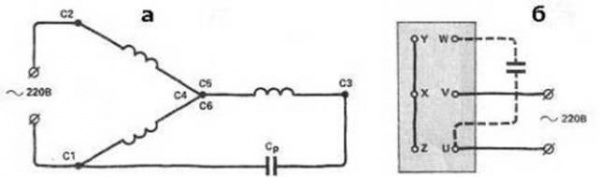
The first thing that had to be done was to change the connection diagram of the electric motor windings from "star" to "triangle", observing the polarity of the connection of the windings (beginning - end) (Fig. 1). This switching allows the electric motor to be connected to a single-phase 220 V.
The power of the sewing machine electric motor according to the plate is 0.4 kW. To acquire working, and even more so starting metal-paper capacitors such as MBGO, MBGP, MBGCH with a capacity of 50 and 100 microfarads, respectively, for an operating voltage of 450 ... 600 V turned out to be an unbearable task due to their high cost in the "flea market". Use instead of metal-scrap polar (electrolytic) capacitors and powerful rectifier diodes D242, D246. positive result did not give. The electric motor stubbornly did not start, apparently due to the finite resistance of the diodes in the forward direction.
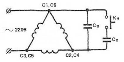
Therefore, an absurd at first glance idea came to mind of starting an electric motor using a short-term connection of a conventional electrolytic capacitor to an alternating current network (Fig. 2). After starting (acceleration) of the electric motor, the electrolytic capacitor is switched off, and the electric motor operates in two-phase mode, while losing up to 50% of its power. But if you foresee a power reserve in advance, or you know that such a stock exists (as in my case), then you can put up with this drawback. By the way, when the electric motor operates with a working phase-shifting capacitor, the electric motor also loses up to 50% of its power.
Now about the most important thing. The electrolytic capacitor, being connected directly to the AC network, heats up quickly, the electrolyte boils, and it explodes - many know this. As the experiment showed, it takes about 10 ... 15 s. It is known that the resistance of a capacitor in an AC circuit of industrial frequency is determined by the formula.
where C is the capacitance of the capacitor in microfarads.
The magnitude of the current in the circuit with the capacitor
But if the electrolytic capacitor is switched on through a small resistance (in my case, this is the complex resistance of the phase of the winding of the electric motor Z \u003d r + jx), and also for a short time, during the acceleration of the electric motor (somewhere 1 ... 1.5 s), then the electrolytic capacitor is not damaged, since it does not have time to warm up.
The short-term activation can be provided by the PNVS-10UHL2 button,
used in household washing machines. The button has three contacts: two - with latching (SB 1.1, SB1.3) and one - without latching (SB 1.2). It turns on the capacitor, and when you stop pressing the button, it returns to its original off position.
The formulas for calculating the starting capacitor have been repeatedly printed, but nevertheless I want to repeat them for the connection diagram of the stator winding of the electric motor in a "triangle".
where U is the mains voltage; In - rated current consumed by the electric motor.
where P is the power of the electric motor, kW; U is the mains voltage. IN; n - coefficient useful action electric motor (usually 0.8 ... 0.9); cosph - power factor (usually 0.85).
Electrolytic capacitors must have a voltage of at least 450 V. It is advisable to collect capacity from several capacitors (the thermal regime is improved). The capacitors are placed in a protective box.
Four years of experience in operating an electric motor has shown the viability of the specified scheme for starting it. This scheme was repeated by some of my friends, however, experiments were carried out with electric motors up to 1 kW. For electric motors over 1 kW, it seems to me that a small current-limiting resistor with a corresponding power dissipation must be connected in series with the capacitor during start-up.
Literature
1. Smirnov K.0. The operation of a three-phase electric motor in a single-phase network. - Radio amateur, 1993, N6, P.27.
2. Kukharenko A. Three-phase electric motor in a single-phase network. - Radio amateur, 1996, N2, P.28.
CONNECTING A THREE-PHASE ASYNCHRONOUS MOTOR
TO SINGLE-PHASE NETWORK 220V
S. RYBAS, Modeler - Constructor, 2/8
Many lovers of tinkering often try to adapt three-phase electric motors for various home-made machines: sharpening, drilling, woodworking and others. But the trouble is - not everyone knows how to power such an electric motor from a single-phase network.
Among different ways starting three-phase electric motors is the simplest and most effective - with the connection of the third winding through a phase-shifting capacitor. The useful power developed by the electric motor is 50-60% of its power in three-phase mode. However, not all three-phase motors work well on a single-phase network. These include, for example, the MA series squirrel cage double-cage electric motors. Therefore, preference should be given to three-phase electric motors of series A, DO, AO2, AOL, APN, UAD, etc.
- For an electric motor with a capacitor start to work normally, the capacitance of the capacitor must change depending on the number of revolutions. Since in practice this condition is difficult to fulfill, the motor is usually controlled in two stages - first it is turned on with a starting capacitor, and after acceleration, it is disconnected, leaving only a working capacitor.
- If the motor passport indicates a voltage of 220/380 V, then you can turn on the motor into a single-phase network with a voltage of 220 V according to the diagram shown in Figure 1. When you press the SB1 button, the M1 electric motor starts to accelerate, and when it picks up speed, the button is released - SB1 .2 opens, while SB1.1 and SB1.3 remain closed. They are opened to stop the motor.
R and C. one. Electrical diagram inclusion of a three-phase electric motor in a single-phase network.
When connecting the windings of the electric motor in a "triangle", the capacity of the working capacitor is determined by the formula: where Cp is the capacitance of the capacitor, μF; I is the current consumed by the electric motor, A; U - mains voltage, V.
If the power of the electric motor is known, the current consumed by it is determined by the formula: ![]() where P is the power of the electric motor (indicated in the passport), W; U - mains voltage, V; n -
Efficiency; cosph -
Power factor.
where P is the power of the electric motor (indicated in the passport), W; U - mains voltage, V; n -
Efficiency; cosph -
Power factor.
The capacity of the starting capacitor is chosen 2-2.5 times more than the working one, and their permissible voltages should be at least 1.5 times higher than the mains voltage. For a 220 V network, it is better to use capacitors of the MBGO, MBGP, MBGCH brands with an operating voltage of 500 V and above. Electrolytic capacitors K50-3, EGTs-M, KE-2 with an operating voltage of at least 450 V (subject to short-term switching on) can also be used as starting ones. For greater reliability, they are switched on according to the scheme shown in Figure 2. The total capacity is equal to C / 2. Shunt the starting capacitors with a 200-500 kOhm resistor, through which the remaining electric charge will “drain”.
Figure: 2. Connection diagram of electrolytic capacitors.
The operation of an electric motor with a capacitor start has some features. When operating in idle mode, a current flows through the winding fed through the capacitor, which is 20-40% higher than the rated one. Therefore, if the electric motor will often be used in an underloaded or idle mode, the capacitance of the capacitor Cp should be reduced. In case of an overload, the electric motor may stop, then to start it, reconnect the starting capacitor (by removing or reducing to a minimum the load on the shaft). In practice, the values \u200b\u200bof the capacitances of the working and starting capacitors, depending on the power of the electric motor, are determined from the table.
| Three-phase electric motor power, kW | ||||||
| Minimum capacitance of the capacitor Ср, μF | ||||||
| Starting capacitor capacity (Cn), microfarad |
To start the electric motor on idling or with a small load, the capacitance of the capacitor Cn can be reduced. For example, to turn on an AO2 electric motor with a power of 2.2 kW at 1420 rpm, a 230 μF capacitor can be used as a working capacitor, and a 150 μF starting one. In this case, the electric motor starts confidently with a small load on the shaft. The reversal of the electric motor is carried out by switching the phase on its winding with the SA1 toggle switch (Fig. 1).
Figure: 3. Electrical diagram of the starting device for a three-phase electric motor with a power of 0.5 kW.
Figure 3 shows an electrical diagram of a portable universal unit for starting three-phase electric motors with a power of about 0.5 kW from a single-phase network without reversing. When you press the SB1 button, magnetic switch KM1 (toggle switch SA1 is closed) and by its contact system KM1.1, KM1.2 connects the electric motor M1 to the 220 V network. At the same time, the third contact group KM1.3 blocks the SB1 button. After full acceleration of the electric motor, the starting capacitor C1 is turned off with the SA1 toggle switch. The electric motor is stopped by pressing the SB2 button. The device uses a magnetic starter of the PML type, designed for alternating current voltage 220 V; SB1, SB2 - paired buttons PKE612, SA1-toggle switch T2-1; resistors: R1 - wire PE-20, R2 - MLT-2, C1, C2 - MBGCH capacitors for a voltage of 400 V (C2 is composed of two parallel-connected capacitors of 20 μF X 400 V each); HL1 - lamp KM-24 (24 V, 100 mA). M1 - electric motor 4A71A4 (AO2-21-4) for 0.55 kW, 1420 rpm.
- The starting device is mounted in a tin case with dimensions 170x140x70 mm (Fig. 4). On the top panel there are “Start” and “Stop” buttons, a signal lamp and a toggle switch for turning off the starting capacitor. On the front side wall, a homemade three-pin connector is installed, made of three pieces of copper tube and a round electrical plug, in which a third pin is added.
R and C. four. Appearance starting device: 1 - housing, 2 - carrying handle, 3 - signal lamp, 4 - toggle switch for switching off the starting capacitor, 5 - Start and Stop buttons, 6 - modified electrical plug, 7 - panel with connector sockets.
It is not very convenient to use the SA1 toggle switch (Fig. 3). Therefore, it is better if the starting capacitor is switched off automatically using an additional relay K1 (Fig. 5) of the MKU-48 type. When you press the SB1 button, it works and with its contact pair K1.1 turns on the magnetic starter KM1, and K1.2 - the starting capacitor Cn. In turn, the magnetic starter KM1 is self-locking using its contact system KM1.1, and KM1.2 and KM1.3 connect the electric motor to the network. The SB1 button is kept pressed until the electric motor is fully accelerated, and then released - the K1 relay is de-energized and turns off the starting capacitor, which is discharged through the R2 resistor. At the same time, the magnetic starter KM1 remains on, providing power to the electric motor in operating mode. Stop the electric motor by pressing the SB2 “Stop” button.
Figure: 5. Wiring diagram of the starting device with automatic shutdown condenser Cn.
In conclusion, a few words about the improvements that expand the capabilities of the launcher. Capacitors Cp and Cn can be made composite with steps of 10-20 μF and connected by multi-position switches (or two to four toggle switches), depending on the parameters of the started electric motors. We recommend replacing the HL1 incandescent lamp with a damping wire resistor with a neon one with an additional low-power resistor; instead of paired buttons PKE612, use two single buttons of any type; the fuses can be replaced by automatic fuses with the appropriate cut-off current.
STARTING A THREE-PHASE ENGINE FROM A SINGLE-PHASE MAINS
WITHOUT LOSS OF POWER
"Radio" No. 7, 2000
S. BIRYUKOV, Moscow
In various amateur electromechanical machines and devices, three-phase asynchronous squirrel-cage motors are most often used. Unfortunately, a three-phase network in everyday life is an extremely rare phenomenon, therefore, to power them from a conventional electrical network amateurs use a phase-shifting capacitor, which does not allow to fully realize the power and starting characteristics of the engine. The existing SCR "phase-shifting" devices further reduce the power on the motor shaft.
A variant of the diagram of the device for starting a three-phase electric motor without power loss is shown on fig. one... The windings of the 220/380 V motor are delta-connected, and the capacitor C1 is connected, as usual, in parallel with one of them. The capacitor is "helped" by the choke L1, connected in parallel with the other winding.
With a certain ratio of the capacitance of the capacitor C1, the inductance of the inductor L1 and the load power, it is possible to obtain a phase shift between the voltages on the three load branches, equal to exactly 120 °. On fig. 2 a vector diagram of voltages for the device shown in fig. one, with a purely active load R in each branch.
Linear current Il in vector form is equal to the difference of currents Ic and Ia, and in absolute value corresponds to the value of Iph, where Iph \u003d I1 \u003d I2 \u003d I3 \u003d Ul / R is the phase load current, Ul \u003d U1 \u003d U2 \u003d U3 \u003d 220 V - linear mains voltage.
A voltage Uc1 \u003d U2 is applied to the capacitor C1, the current through it is equal to Ic1 and is ahead of the voltage by 90 ° in phase. Similarly, the voltage UL1 \u003d U3 is applied to the choke L1, the current through it IL1 lags behind the voltage by 90 °. If the absolute values \u200b\u200bof the currents Ic1 and IL1 are equal, their vector difference with the correct choice of capacitance and inductance can be equal to Il. The phase shift between the currents Ic1 and IL1 is 60 °, therefore the triangle of the vectors Il, Ic1 and IL1 is equilateral, and their absolute value is Ic1 \u003d IL1 \u003d Il \u003d If.
In turn, the phase load current Iph \u003d P / ЗUL, where P is the total load power. In other words, if the capacitance of the capacitor C1 and the inductance of the choke L1 are chosen such that when a voltage of 220 V is applied to them, the current through them would be equal to Ic1 \u003d IL1 \u003d P / (Ul) \u003d P / 380, shown in fig. one the L1C1 circuit will provide a three-phase voltage to the load with accurate phase displacement.
IN tab. one the values \u200b\u200bof the current Ic1 \u003d IL1 are given. the capacitance of the capacitor C1 and the inductance of the choke L1 for different values \u200b\u200bof the total power of the purely active load.
A real load in the form of an electric motor has a significant inductive component. As a result, the linear current lags in phase from the active load current by a certain angle φ of the order of 20 ... 40 °. On the nameplates of electric motors, it is usually not the angle that is indicated, but its cosine - widely known, equal to the ratio of the active component of the line current to its total value.
The inductive component of the current flowing through the load of the device shown in fig. one, can be represented in the form of currents passing through some inductors Lн, connected in parallel with the active resistances of the load (Fig. 3, a), or equivalently parallel to C1, L1 and mains wires.
Of fig. 3, b it is seen that since the current through the inductance is antiphase to the current through the capacitor, the LH inductors decrease the current through the capacitive branch of the phase-shifting circuit and increase through the inductive one. Therefore, to maintain the phase of the voltage at the output of the phase-shifting circuit, the current through the capacitor C1 must be increased and reduced through the coil.
The vector diagram for a load with an inductive component becomes more complicated. A fragment of it that allows you to make the necessary calculations is shown on rice 4 equal to 0.85 to 0.9.
IN tab. 2 the values \u200b\u200bof the currents Ie1, IL1 flowing through the capacitor C1 and the choke L1 are given at various values \u200b\u200bof the total load power having the above value
For such a phase-shifting circuit, capacitors MBGO, MBGP, MBGT, K42-4 are used for an operating voltage of at least 600 V or MBGCH, K42-19 for a voltage of at least 250 V. The choke is easiest to make from a rod-type power transformer from an old tube TV. The no-load current of the primary winding of such a transformer at a voltage of 220 V usually does not exceed 100 mA and has a nonlinear dependence on the applied voltage.If a gap of the order of 0.2-1 mm is introduced into the magnetic circuit, the current will increase significantly, and its dependence on voltage will become linear.
The mains windings of the vehicle transformers can be connected so that rated voltage they will be 220 V (jumper between pins 2 and 2 "), 237 V (jumper between pins 2 and 3") or 254 V (jumper between pins 3 and 3 ") Mains voltage is most often applied to pins 1 and 1". Depending on the type of connection, the inductance and winding current change. 3 shows the current values \u200b\u200bin the primary winding of the TC-200-2 transformer when a voltage of 220 V is applied to it at different gaps in the magnetic circuit and different switching on of the winding sections Comparison of the data in Tables 3 and 2 allows us to conclude that the specified transformer can be installed in the phase-shifting circuit of the motor with with a power of about 300 to 800 W and, choosing the gap and the switching circuit of the windings, obtain the required current. The inductance also changes depending on the in-phase or anti-phase connection of the mains and low-voltage (for example, filament) transformer windings. The maximum current may slightly exceed rated current in working mode. In this case, to facilitate the thermal regime, it is advisable to remove all secondary windings from the transformer; some of the low-voltage windings can be used to power the automation circuits of the device in which the electric motor operates.
IN tab. four nominal currents are given primary windings transformers of various TVs and guide values engine power, with which it is advisable to use them, the phase-shifting LC-circuit should be calculated for the maximum possible load of the electric motor.
At a lower load, the required phase shift will no longer be maintained, but the starting characteristics will improve compared to using a single capacitor. Experimental verification was carried out both with a purely active load and with an electric motor. The active load functions were performed by two parallel-connected 60 and 75 W incandescent lamps included in each load circuit of the device. (see pic 1), which corresponded to a total power of 400 W In accordance with table 1 the capacitance of the C1 capacitor was 15 μF The gap in the magnetic circuit of the ТС-200-2 transformer (0.5 mm) and the winding connection scheme (at 237 V) were chosen to ensure the required current of 1.05 A. The voltages U1, U2 measured on the load circuits , U3 differed from each other by 2 .. 3 V, which confirmed the high symmetry of the three-phase voltage.
The experiments were also carried out with a three-phase asynchronous motor with a squirrel-cage rotor AOL22-43F with a power of 400 W [3]. He worked with a capacitor C1 with a capacity of 20 microfarads (by the way, the same as when the engine was running with only one phase-shifting capacitor) and with a transformer, the gap and connection of the windings of which were selected from the condition of obtaining a current of 0.7 A. As a result, it was possible to quickly start the engine without starting capacitor and noticeably increase the torque felt when the pulley is braking on the motor shaft. Unfortunately, it is difficult to carry out a more objective check, since it is almost impossible to provide a normalized mechanical load on the engine in an amateur environment.
It should be remembered that the phase-shifting circuit is a series oscillatory circuit tuned to a frequency of 50 Hz (for a purely resistive load option), and this circuit cannot be connected to the mains without load.
LITERATURE
1 Kuzinets L. M., Sokolov V. S. Nodes of television receivers - M Radio and communication 1987
2 Sidorov I.N., Binnatov M.F., Vasiliev E.A. Power supply devices for household CEA - M Radio and communication, 1991
3 Biryukov S. Automatic pumping station. - Radio, 1998, No. 5, p.45.46.
ELECTRONIC START OF A THREE-PHASE ENGINE
FROM SINGLE-PHASE NETWORK
A. DUBROVSKY, Novopolotsk, Vitebsk region, Belarus
In the home "workshops" of radio amateurs there are electromechanical machines and various devices driven by three-phase asynchronous motors. However, in everyday life, a three-phase network is often absent, therefore a phase-shifting capacitor is often used to power them. Unfortunately, this leads to a decrease in required power on the shaft of the electric motor and, moreover, the possibility of speed control is excluded. Using the proposed device, it is possible not only to supply a three-phase asynchronous electric motor from a single-phase network, but also to smoothly regulate its rotation frequency.
The speed controller significantly improves the characteristics of the three-phase asynchronous motor (TAD). The described device makes it possible to supply the TAD from a single-phase network with practically no loss of power, to regulate the starting torque, to regulate the rotational speed within wide limits both at idle and under load, and also, most importantly, to increase maximum frequency rotation is more than nominal.
The proposed device is operated with a 120 W TAD and rated frequency rotation 3000 rpm.
As you know, there are several ways to regulate the speed of TAD - by changing the supply voltage, load on the shaft, using a special rotor winding with adjustable resistance. However, the most effective is frequency regulation, since it allows you to maintain energy characteristics and use the cheapest and most reliable electric motors with a short-circuited rotor winding - "squirrel cage".
SPEED REGULATOR FOR THREE-PHASE ASYNCHRONOUS MOTORS
A schematic diagram of the rotation controller of a three-phase asynchronous motor is shown in Fig. 1. On elements DD1.1-DD1.3 a master oscillator is assembled with a frequency variable within 30 ... 800 Hz. Regulate the frequency with a variable resistor R3. Counter DD2, element AND NOT DD1.4 and four elements Exclusive OR DD3.1-DD3.4 are part of the three-phase sequence pulse generator (FIT), which converts constant pressure into rectangular signals, phase-shifted by 120 degrees. In fig. 2 shows the stress diagrams at characteristic points.
Three identical amplifiers are assembled on transistors 1VT1-1VT6, 2VT1-2VT6, 3VT1-3VT6, one for each phase of the TAD. In fig. 1 shows a diagram of only one amplifier. The schemes for the rest are exactly the same. Let's consider the work of one of them (the top one according to the scheme). When a high level appears at the output of element DD3.2, the composite transistor 1VT4, 1VT5 opens, and the output transistor 1VT6 is closed. In addition, a high level is fed to the input of the 1U1 transistor optocoupler, as a result of which a low level is set at its output, which closes the composite transistor 1VT1, 1VT2. The output transistor 1VT3 is open. For voltage decoupling, transistors 1VT1, 1VT2 and 1VT4, 1VT5 are powered from different sources with a voltage of +10 V, and transistors 1VT3, 1VT6 - from a voltage source of +300 V. Diodes 1VD3, 1VD4, 1VD6, 1VD7 serve for more reliable closing of the output transistors.
One of the main conditions for the normal operation of 1VT3 and 1VT6 transistors is that they should not be simultaneously open. For this, the control voltage is supplied to the input of the composite transistor 1VT1, 1VT2 from the output of the optocoupler 1U1, which provides a certain delay in its switching (approximately 40 μs). When a high level optocoupler appears at the input, the capacitor 1C2 begins to charge. The low-level signal at the optocoupler input cannot instantly close the composite transistor 1VT4, 1VT5, since the capacitor 1C2, discharging along the 1R3 circuit, the emitter junctions of the transistors, maintains it for about 140 μs in the open state, and the 1VT6 transistor in the closed state. The optocoupler turn-off time is approximately 100 μs, so the 1VT3 transistor closes before the 1VT6 transistor opens.
Diodes 1VD5, 1VD8 protect the output transistors from an increase in voltage when switching inductive load - TAD windings, and also close the current of the windings when the voltage across them changes its polarity (when switching transistors 1VT3, 1VT6). For example, after closing the transistors 1VT3 and 2VT6, the current flows for some time in the same direction - from phase A to phase B, closing through the diode 2VD5, the power supply, diode 1VD8, until it decreases to zero.
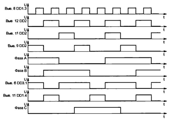
Let us consider the switching sequence of the output transistors using the example of phases A and B. When transistors 1VT3 and 2VT6 are open, the current flows through the circuit: a source of +300 V, the collector-emitter section of the 1VT3 transistor, the windings of phase A and phase B, the collector-emitter section of the 2VT6 transistor. When these transistors turn off and 1VT6 and 2VT3 turn on, current flows in the opposite direction. Thus, voltage pulses of a rectangular shape with a phase shift of 120 degrees are applied to phases A, B and C. (fig. 2). The frequency of the supply voltage TAD is determined by the switching frequency of these transistors. Due to the alternate opening of the transistors, the current sequentially passes through the stator windings AB-AC-VS-VA-SA-SV-AB, which creates a rotating magnetic field. The circuit for constructing the output stages described above is a three-phase bridge. Its advantage lies in the fact that there are no third harmonic components in the phase current.
The regulator's power supply generates voltages of +5, +10 and +300 V. The +5 V voltage generated by the stabilizer on the VD3 Zener diode and the VT1 transistor is used to power the DD1-DD3 microcircuits. The upper composite transistor of each amplifier is powered by a separate winding of the T1 mains transformer and a separate bridge rectifier (WD1, 2VD1, 3VD1). The lower composite transistor of all amplifiers - from winding II and diode bridge VD2. The VD1 bridge and the C2L1C3 LC filter are used to power the output transistors. The capacity of the capacitors C2 and C3 is selected based on the power of the TAD. It must be at least 20 μF with a choke inductance of 0.1 H.
Constant resistors MLT, OMLT, VS can be used in the regulator. Capacitor C1 - any, for example, ceramic К10-17-26, С2-С5, 1С1, 2С1, ЗС1 - any oxide. Choke L1 - homemade. It is wound on a W-shaped magnetic wire with a cross-sectional area of \u200b\u200b4 cm2. The winding contains 120 turns of wire PEV 0.35. The choke can be eliminated, but you will have to increase the capacity of the capacitors C2 and C3 to 50 μF. Optocouplers 1U1, 2U1, 3U1 can also be used with others whose turn-on delay time is not more than 100 μs, and the isolation voltage is not less than 400 V.
The main requirement for transistors is a high and approximately the same current transfer coefficient for all (at least 50). KT315A transistors can be interchangeable with transistors of the KT315, KT312, KT3102 series with any letter indices, and KT817A transistors (VT1, 1VT2, 1VT5, 2VT2, 2VT5, 3VT2. 3VT5) - on KT817 or KT815 letters with any. Instead of transistors KT858A, you can use any powerful with permissible voltage collector-emitter not less than 350 V and current transfer coefficient not less than 50. They should be installed on heat-water with an area of \u200b\u200bnot less than 10 cm2 each.
However, when using electric motors with a power of more than 200 W, heatsinks with a larger area will be required. If the TAD power exceeds 300 W, instead of the KTs409A rectifier, it is necessary to assemble a bridge from individual diodes designed for a reverse voltage of more than 400 V and the corresponding current. Diodes 1VD5, 1VD8 are suitable for any with a permissible forward impulse current of at least 5 A and a reverse voltage of at least 400 V, for example, KD226V or KD226G. Transformer - any power of at least 15 W, having four separate secondary windings of 8 ... 9 V each.
When setting up the device, first turn off the voltage of +300 V and check the presence of all signals in accordance with Fig. 2. If necessary, by selecting the capacitor C1 or the resistor R2, the frequency at the collector of the 1VT2 (1VT5) transistor is changed within 5 ... 130 Hz. Then, when the TAD is off, instead of +300 V, a voltage of +100 ... 150 V is supplied from an external source, the collector and emitter of the 1VT2 transistor, the collector and emitter of the 1VT5 transistor (to close the 1VT3 and 1VT6 transistors) are closed and the current in the collector circuit of the 1VT3 transistor is measured, which should be no more than a few milliamps - the leakage current of the output transistors.
Further, the collectors and emitters of the above transistors are opened and the maximum frequency is set with the resistor R2. By selecting a capacitor 1C2 (in the direction of increasing capacity), the minimum current in the collector circuit of the 1VT3 transistor is achieved. The rest of the amplifiers are adjusted in the same way. After that, an electric motor is connected to the output of the regulator, the windings of which are connected by a star. Instead of +300 V, a voltage is supplied from an external source within +100 ... 150 V. The rotor of the electric motor should start rotating. When it is necessary to change the direction of rotation, swap any two TAD phases. If the output transistors operate in the correct mode, they remain slightly warm for a long time, otherwise the resistance of the resistors 1R6, 1R8, 2R6, 2R8, 3R6, 3R8 is selected.
Literature
1. Radin V.I. Electric cars: Asynchronous machines. - M .: graduate School. 1988.
2. Kraachik AE Selection and application of asynchronous motors. - M .: Energoatom publ. 1987.
3. Lopukhina EM Asynchronous executive micromotors for automation systems. - M .: Higher school, 1988.
In life, there are situations when you need to start a 3-phase asynchronous electric motor from a household network. The problem is that you only have one phase and zero at your disposal.
What to do in such a situation? Can a three-phase motor be connected to a single-phase network?
If you approach work wisely, everything is real. The main thing is to know the basic schemes and their features.
Design features
Before starting work, understand the design of the IM (induction motor).
The device consists of two elements - a rotor (moving part) and a stator (stationary unit).
The stator has special grooves (grooves), into which the winding is placed, distributed so that the angular distance is 120 degrees.
The windings of the device create one or more pairs of poles, the number of which determines the frequency with which the rotor can rotate, as well as other parameters of the electric motor - efficiency, power and other parameters.
When an asynchronous motor is connected to a network with three phases, current flows through the windings at different time intervals.
A magnetic field is created that interacts with the rotor winding and causes it to rotate.
In other words, an effort appears that turns the rotor at different time intervals.
If you connect the blood pressure to a network with one phase (without performing preparatory work), the current will appear in only one winding.
The torque generated will not be enough to displace the rotor and keep it rotating.
That is why in most cases the use of starting and working capacitors is required to ensure the operation of a three-phase motor. But there are other options as well.
How to connect an electric motor from 380 to 220V without capacitor?
As noted above, a capacitor is most often used to start an EM with a squirrel-cage rotor from a network with one phase.
It is he who ensures the start of the device at the first moment of time after the single-phase current... In this case, the capacity of the starting device should be three times higher than the same parameter for the working capacity.
For HELLs with a power of up to 3 kilowatts and used at home, the price of starting capacitors is high and sometimes commensurate with the cost of the motor itself.
Consequently, many are increasingly avoiding containers that are used only at the time of start-up.
The situation is different with working capacitors, the use of which allows the motor to load at 80-85 percent of its power. In the absence of them, the power indicator can drop to 50 percent.
Nonetheless, capacitor-free start A 3-phase motor from a single-phase network is possible thanks to the use of bidirectional keys that work for short periods of time.
The required torque is provided due to the displacement of the phase currents in the IM windings.
Today, two schemes are popular, suitable for motors up to 2.2 kW.
It is interesting that the start-up time of the IM from a single-phase network is not much lower than in the usual mode.
The main elements of the circuit are triacs and symmetrical dinistors. The first ones are controlled by bipolar pulses, and the second - by signals coming from the half-cycle of the supply voltage.
Scheme No. 1.
Suitable for 380 Volt motors with speeds up to 1,500 rpm with delta-connected windings.
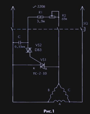
An RC circuit acts as a phase shifter. By changing the resistance R2, it is possible to achieve a voltage across the capacitance shifted by a certain angle (relative to the voltage of the household network).
Performance main task takes over the symmetrical dinistor VS2, which at a certain point in time connects the charged capacitance to the triac and activates this key.
Scheme No. 2.
Suitable for electric motors with a speed of up to 3000 rpm and for blood pressure, characterized by increased resistance at the time of start.
These motors require more starting current, therefore, the open star circuit is more relevant.
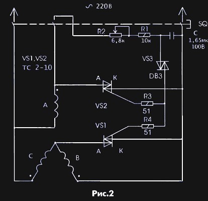
Feature - the use of two electronic switches replacing phase-shifting capacitors. During the adjustment process, it is important to ensure the required shift angle in the phase windings.
This is done as follows:
- The voltage is supplied to the electric motor through a manual starter (it must be connected in advance).
- After pressing the button, it is required to select the starting moment using the resistor R
When implementing the considered schemes, it is worth considering a number of features:
- For the experiment, we used non-radiator triacs (types TS-2-25 and TS-2-10), which proved to be excellent. If you use triacs on a plastic case (imported), you cannot do without radiators.
- Symmetrical dynistor type DB3 can be replaced by KP Despite the fact that the KP1125 is made in Russia, it is reliable and has less switching voltage. The main disadvantage is the scarcity of this dinistor.
How to connect through capacitors
First, decide which circuit is assembled on ED. To do this, open the lid-bar, where the blood pressure terminals are led out, and see how many wires come out of the device (most often there are six).
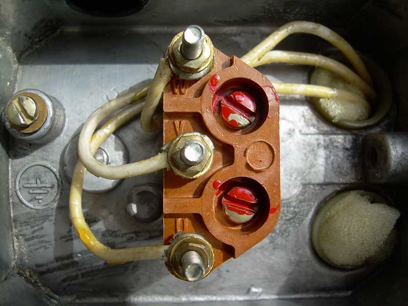
The designations are as follows: C1-C3 - the beginning of the winding, and C4-C6 - its ends. If the beginnings or ends of the windings are joined together, this is a "star".
The situation is most difficult if six wires simply come out of the case. In this case, you need to look for the corresponding designations on them (C1-C6).
To implement the scheme for connecting a three-phase ED to a single-phase network, two types of capacitors are required - starting and working.
The first are used to start the electric motor at the first moment. As soon as the rotor spins up to the required number of revolutions, the starting capacity is excluded from the circuit.
Failure to do so could result in serious consequences such as damage to the motor.
The main function is taken over by working capacitors. Here it is worth considering the following points:
- Working capacitors are connected in parallel;
- The rated voltage must be at least 300 volts;
- The capacity of the working capacities is selected taking into account 7 μF per 100 W;
- It is desirable that the type of working and starting capacitor be identical. Popular options are MBGP, MPGO, KBP and others.
If you take these rules into account, you can extend the operation of the capacitors and the electric motor as a whole.
The calculation of the capacity should be made taking into account rated power ED. If the motor is underloaded, overheating is inevitable, and then the capacity of the working capacitor will have to be reduced.
If you choose a capacitor with a capacity less than the permissible, then the efficiency of the electric motor will be low.
Remember that even after the circuit is turned off, the voltage remains on the capacitors, so it is worth discharging the device before starting work.
Also note that connecting an electric motor with a power of 3 kW or more to ordinary wiring is prohibited, because this can lead to a shutdown or burnout of plugs. In addition, the risk of melting the insulation is high.
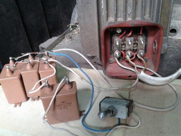
To connect ED 380 to 220V using capacitors, proceed as follows:
- Connect the containers together (as mentioned above, the connection must be parallel).
- Connect the parts with two wires to the EM and an alternating single-phase voltage source.
- Start the engine. This is done to check the direction of rotation of the device. If the rotor moves in the desired direction, no further manipulation is required. Otherwise, the wires connected to the winding should be reversed.
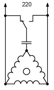
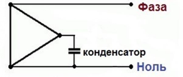
With a capacitor, an additional simplified one - for a star circuit.
With a capacitor, an additional simplified one - for a triangle circuit.
How to connect with reverse
There are situations in life when you need to change the direction of rotation of the motor. This is also possible for three-phase EMs used in a household network with one phase and zero.
To solve the problem, it is required to connect one output of the capacitor to a separate winding without the possibility of rupture, and the second - with the possibility of transferring from "zero" to "phase" winding.
To implement the circuit, you can use a switch with two positions.
Wires from "zero" and "phase" are soldered to the extreme terminals, and a wire from the capacitor is connected to the central one.
How to connect in a star-delta pattern (with three wires)
For the most part, in the ED of domestic production, a star diagram has already been assembled. All that is required is to rebuild the triangle.
The main advantage of the star / delta connection is the fact that the motor delivers maximum power.
Despite this, such a scheme is rarely used in production due to the complexity of the implementation.
Three starters are required to connect the motor and make the circuit work.
The current is connected to the first (K1), and the stator winding to the other. The remaining ends are connected to the K3 and K2 starters.
When the K3 starter is connected to the phase, the remaining ends are shortened, and the circuit is converted into a "star".
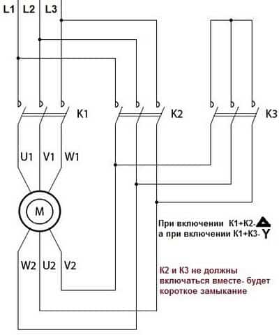
Please note that the simultaneous inclusion of K2 and K3 is prohibited due to the risk of a short circuit or knocking out the AB supplying the EM.
To avoid problems, a special interlock is provided, which means that one starter is disconnected when the other is turned on.
The principle of the circuit is simple:
- When the first starter is connected to the network, the time relay starts and supplies voltage to the third starter.
- The engine starts in a star pattern and starts to run at higher power.
- After some time, the relay opens the contacts of K3 and connects K2. In this case, the electric motor works according to the "triangle" scheme with a reduced power. When you need to turn off the power, K1 turns on.
Outcome
As you can see from the article, connect the electric motor three-phase current into a single-phase network without power loss is real.
At the same time, for home conditions, the simplest and most affordable option is using a starting capacitor.
IT MAY BE INTERESTING:
There are often cases when it is necessary to connect an electric motor to a 220 volt network - this happens when trying to connect the equipment to your needs, but the circuit does not answer technical specificationsspecified in the passport of such equipment. We will try to disassemble in this article the main methods for solving the problem and present several alternative schemes with a description for connecting a single-phase electric motor with 220 volt condensate.
Why is this happening? For example, in a garage you need to connect a 220 volt asynchronous electric motor, which is designed for three phases. At the same time, it is necessary to preserve the efficiency (efficiency), this is done if the alternative (in the form of an engine) simply does not exist, because a rotating magnetic field is easily formed in a three-phase circuit, which ensures the creation of conditions for the rotation of the rotor in the stator ... Without this, the efficiency will be less than three-phase circuit connections.
When there is only one winding in single-phase motors, we observe a picture when the field inside the stator does not rotate, but pulsates, that is, the start-up push does not occur until the shaft is unwound with our own hands. In order for the rotation to occur independently, we add an auxiliary starting winding. This is the second phase, it is moved 90 degrees and pushes the rotor when turned on. In this case, the motor is still connected to the network with one phase, so that the name of the single-phase is retained. Such single-phase synchronous motors have a working and starting winding. The difference is that the starting operates only when turned on, starting the rotor, working for only three seconds. The second winding is on all the time. In order to determine where which one, you can use a tester. In the figure, you can see their relationship with the scheme as a whole.
Connecting a 220 volt electric motor: the motor is started by supplying 220 volts to the working and starting windings, and after gaining the required speed, you need to manually turn off the starting one. In order to shift the phase, an ohmic resistance is needed, which is provided by the inductance capacitors. There is resistance both in the form of a separate resistor and in the part of the starting winding itself, which is performed according to the bifilar technique. It works like this: the inductance of the coil is maintained, but the resistance becomes greater due to the elongated copper wire. Such a scheme can be seen in Figure 1: connecting a 220 volt electric motor.
Figure 1. Wiring diagram for a 220 volt electric motor with a capacitor
There are also motors in which both windings are continuously connected to the network, they are called two-phase, because the field inside rotates, and the capacitor is provided to shift the phases. For such a circuit to work, both windings have a wire with an equal cross-section to each other.
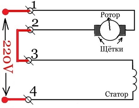
Wiring diagram for a collector motor for 220 volts
Where can you find it in everyday life?
Electric drills, some washing machines, rotary hammers and grinders have a synchronous commutator motor. It is capable of operating in single-phase networks even without starters. The scheme is as follows: ends 1 and 2 are connected with a jumper, the first originates in the armature, the second in the stator. The two tips that remain must be connected to a 220 volt power supply.
Connecting a 220 volt electric motor with a starting winding
Attention!
- Such a scheme excludes the electronics unit, and therefore the motor immediately from the moment of start will work at full power - at maximum speed, literally breaking off with force from the starting electric current, which causes sparks in the collector;
- there are electric motors with two speeds. They can be identified by the three ends in the stator protruding from the winding. In this case, the speed of the shaft during connection decreases, and the risk of deformation of the insulation at start increases;
- the direction of rotation can be changed, for this it is necessary to swap the ends of the connection in the stator or armature.
Wiring diagram for an electric motor 380 to 220 volts with a capacitor
There is another option for connecting an electric motor with a power of 380 volts, which starts moving without load. This also requires a capacitor in working order.
One end connects to zero, and the other to the exit of the triangle with ordinal number three. To change the direction of rotation of the electric motor, it is worth connecting it to the phase, and not to zero.
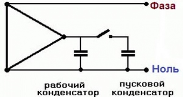
Connection diagram of a 220 volt electric motor through capacitors
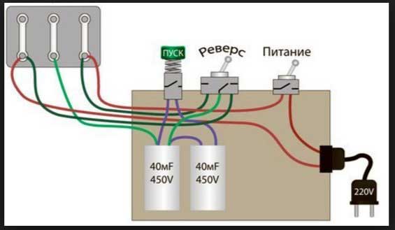
In the case when the engine power is more than 1.5 Kilowatts or when it starts running immediately with a load, together with the working capacitor, it is necessary to install the starting capacitor in parallel. It serves to increase the starting torque and turns on for just a few seconds during start. For convenience, it connects with a button, and the entire device is powered by a toggle switch or a button with two positions, which has two fixed positions. In order to start such an electric motor, you need to connect everything through a button (toggle switch) and hold the start button until it starts. When it starts, just release the button and the spring opens the contacts, disconnecting the starter
The specificity lies in the fact that asynchronous motors are originally intended to be connected to a network with three phases of 380 V or 220 V.
Important! In order to connect a single-phase electric motor to a single-phase network, you need to familiarize yourself with the motor data on the tag and know the following:
P \u003d 1.73 * 220 V * 2.0 * 0.67 \u003d 510 (W) calculation for 220 V
P \u003d 1.73 * 380 * 1.16 * 0.67 \u003d 510.9 (W) calculation for 380 V
The formula makes it clear that electric power superior to mechanical. This is the necessary margin for compensating for power losses at the start - creating a torque of the magnetic field.
There are two types of windings - star and delta. From the information on the motor tag, you can determine which system is used in it.
This is a star winding circuit
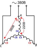
The red arrows are the voltage distribution in the motor windings, which indicates that the voltage of a single phase of 220 V is distributed on one winding, and the line voltage of 380 V is distributed on the other two. Such a motor can be adapted for a single-phase network according to the recommendations on the tag: find out for which windings are created, you can connect them with a star or a triangle.
The triangle winding circuit is simpler. If possible, it is better to use it, since the motor will lose power in a smaller amount, and the voltage across the windings will everywhere be equal to 220 V.
This is a connection diagram with a capacitor of an induction motor in a single-phase network. Includes working and starting capacitors.
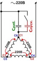
Important! If, at the start, the starting capacitors are not turned off in time, when the motor picks up the standard speed for it, they will lead to a large current imbalance in all windings, which simply ends with overheating of the electric motor.
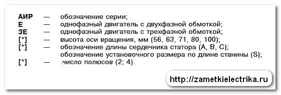
Hello, dear readers and guests of the "Notes of an Electrician" website.
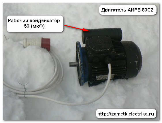
A few days ago, one of my readers contacted me with a request to connect single phase motor series AIRE 80S2. In fact, this motor is not entirely single-phase. It will be more accurate and more correct to classify it as a two-phase induction capacitor motor. Therefore, this article will focus on connecting just such motors.
So, we have a single-phase asynchronous capacitor motor AIRE 80S2, which has the following technical data:
- power 2,2 (kW)
- rotation speed 3000 rpm
- Efficiency 76%
- cosφ \u003d 0.9
- operating mode S1
- mains voltage 220 (V)
- degree of protection IP54
- the capacity of the working capacitor is 50 (μF)
- working capacitor voltage 450 (V)
This motor is installed on a small-sized drilling rig and we need to connect it to the 220 (V) electrical network.
In this article, I will not give the overall and installation dimensions of the AIRE 80C2 single-phase motor. They can be found in the passport for this engine. Let's move on to connecting it.
Connecting a capacitor single-phase motor
An asynchronous capacitor single-phase motor consists of two identical windings that are spaced relative to each other by 90 electrical degrees:
Home or work (U1, U2)
Auxiliary or Launcher (Z1, Z2)
The main (working) winding of such a motor is connected directly to a single-phase network. The auxiliary (starting) winding is connected to the same network, but only through a working capacitor.
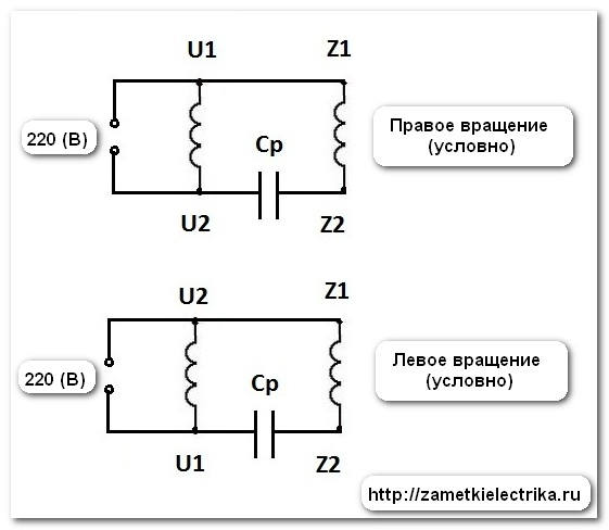
At this stage, many electricians are confused and mistaken, because in a conventional asynchronous single-phase motor, the auxiliary winding must be disconnected after starting. Here, the auxiliary winding is always energized, i.e. at work. This means that a single-phase capacitor motor has a rotating magnetomotive force (MDF) throughout the entire working process. That is why, in terms of its characteristics, it is practically not inferior to three-phase ones. But nevertheless, he has disadvantages:
Low starting torque
Low overload capacity
For our single-phase motor AIRE 80C2, the capacity of the working capacitor is already known (from the passport), and it is 50 (μF). In general, you can independently calculate the capacity of the working capacitor, but this formula is quite complicated, so I will not give it to you.
If you do not know (or have forgotten) how to measure the capacitance, then I will remind you that I already wrote an article on how to use a digital multimeter when measuring the capacitance of a capacitor. Read, everything is described in detail there.
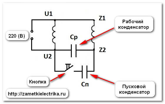
If, according to the conditions for starting a single-phase motor, a higher torque is required, then a starting capacitor must be connected in parallel with the working capacitor during start-up, the capacity of which is chosen empirically to obtain the highest starting torque. From experience I can say that the capacity of the starting capacitor can be taken 2-3 times more than the working one.
Here is an example of connecting a single phase heavy starting capacitor motor:
I told you how to connect and start a 380 Volt motor in a single-phase 220 V. Now I will tell you about how to connect a single-phase electric motor from a broken washing machine, vacuum cleaner, etc. It can be successfully used for other purposes in the household, for example, for drive a sharpener, polisher, lawn mower, etc.
Wiring diagram for a collector motor for 220 volts
In electric drills, hammer drills, grinders and some models of automatic washing machines use a synchronous commutator motor. It successfully starts and operates in single-phase networks without unnecessary starting devices.
For, to connect the collector motor, it is necessary to connect with a jumper two ends No. 2 and No. 3, one coming from the armature, and the other from the stator. And connect the remaining 2 ends to a 220 Volt power supply.
Remember that when connecting a manifold electric motor without an electronics unit, it will work only at maximum speed, and at start there will be a strong jerk, a large starting current, sparking on the collector.
Can be a motor and 2 speed, then the third end will come out of the stator from half of its winding. When connected to it, the speed of rotation of the shaft will decrease, but at the same time the risk of breaking the insulation when starting the motor increases.
To change the direction of rotation it is necessary to swap the ends of the stator or armature connection.
Connection diagrams for single-phase asynchronous electric motors
If there were only one winding in single-phase electric motors in the stator, then the electromagnetic field inside it would be pulsating, and not rotating. And the launch would take place only after unwinding the shaft by hand. Therefore, for self-starting asynchronous motors, an auxiliary winding or starting winding is added, in which the phase is shifted by 90 degrees with the help of a capacitor or inductance. The starting winding pushes the rotor of the electric motor at the moment of switching on. The main connection schemes are shown in the figure.
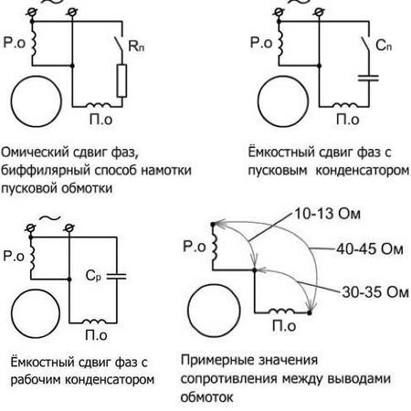
The first two schemes designed to connect the starting winding for the time the motor starts, but not more than 3 seconds in duration. For this, a relay or a start button is used, which must be pressed and held until the motor starts.
Starting winding can be connected through a capacitor, or in very rare cases through a resistance. In the latter case, the winding must be wound using bifilar technology, i.e. the resistance is part of the winding. It increases in it due to the length of the wire, but the inductance of the coil does not change.
In the third most common pattern the capacitor is constantly connected to the network during the operation of the electric motor, and not only during its start-up.
To determine which wires go to each of the windings, first we call them in pairs, and then we measure the resistance of each by. The starting winding will always have more resistance (usually about 30 ohms) than the working winding (most often around 10-13 ohms).
Pick up a capacitor it is necessary for the current consumed by the motor, for example, for I \u003d 1.4 A, a capacitor with a capacity of 6 μF is required.
How to connect a washing machine electric motor
In modern washing machines can stand either collector or three-phase motors. The latter can be started only with the help of an electronic start-regulating device, which will need to be removed from the washing machine and redo the circuit for manual start. But for this you need to be well versed in radio engineering.
The collector motor is the same motor from the washing machine connecting is very simple. 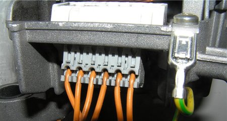 As a rule, 6-7 wires go to the connection block, not counting the grounding of the case.
Two wires come from the tachometer that will not be used. And a pair of wires leaves the stator and the armature (rotor). Also, sometimes one more end may come out from half of the winding. 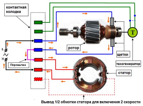
Calling pairs of windings and connect with a jumper the end of the rotor winding with the beginning of the static winding. At the beginning of the rotary, we connect one end of the power supply and the other at the end of the static one.
If you need a second speed connection, then we connect one end of the power supply to the output from half of the winding. She will have less resistance than the whole.
Sometimes an additional pair of contacts from thermal protection can still go to the connection block.
Old Soviet-style washing machines had simple asynchronous electric motors with starting winding. To start them, I recommend using the appropriate relay from the washing machine, which is installed only vertically according to the pointer on the case. The connection is made according to this scheme. 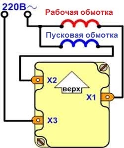
And you can start in a different way only with a working capacitor connected to the starting winding. 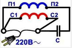
Functional check
For, to check the correctness of the assembled circuit it is necessary to turn on the electric motor and let it run first one minute, and then about 15. If the engine is hot, then the reasons may be:
- Worn, dirty or jammed bearings.
- Large capacity capacitor, turn it off and start the engine by hand, if it stops heating up, reduce the capacitance of the capacitors.
Related materials: