Three-phase electric motors Operating principle. Three-phase asynchronous motor
The fact that asynchronous motors are used today in all industries and agriculture, it is necessary to bow to the Russian engineer M.O. Dolivo-Dobrovolsky. It was he who in 1889 (more precisely on March 8) invented the three-phase asynchronous motor, which converts electricity into mechanical energy (rotation). This, in fact, was a breakthrough in technology and the beginning of a new era.
The most important thing is that electric motors of this type have proven to be very reliable, their production is quite simple, which affects the low cost of the product. Plus a simple design that is easy not only to manufacture, but also to repair. If we look at the statistical data, we can conclude that asynchronous motors are the most produced in the world. They account for up to 90% of the output. So the numbers speak for themselves.
But why are these devices called asynchronous? The whole point is that the rotation speed magnetic field The stator is always greater than the rotation of the rotor. By the way, for electric motors of this type the operating principle is based precisely on the rotation of the magnetic field.
Engine operating principle
To understand how three-phase asynchronous electric motors work, you need to conduct one simple experiment. To do this, you will need a regular horseshoe-type magnet and a copper rod. In this case, the magnet must be well secured to the handle, with the help of which it can be rotated in one place around its axis. A copper rod is secured in bearings and installed in the space between the ends (poles) of a horseshoe magnet. That is, the rod appears to be inside the magnet, or, more precisely, inside its plane of rotation.
Now you just need to rotate the magnetic device by the handle. It's better clockwise. Since there is a magnetic field between the poles, it will also rotate. In this case, the field will intersect or dissect the copper cylinder rod with its lines of force. And then the law comes in electromagnetic induction. That is, eddy currents will begin to appear inside the copper rod. They, in turn, will begin to form their own magnetic field, which will interact with the main magnetic field.
In this case, the rod will begin to rotate in the same direction as the magnet. And here one point arises, which also lies in the principle of operation of the electric motor. It has already been mentioned. If the rotation speed of the rod is the same as that of the magnet, then their power lines will not intersect. That is, there will be no rotation due to the absence of eddy currents.
And a couple more nuances:
- The magnetic field rotates at the same speed as the magnet itself, so the speed is called synchronous.
- But the rod rotates at a lower speed, which is why it is called asynchronous. Hence, in principle, the name of the electric motor itself.
Attention! The difference in the rotation speeds of the magnetic fields is not very large. This quantity is called slip.
By the way, it is not difficult to determine the amount of slip; for this you need to use the formula:
S=n-n1/n, where
- S is the amount of slip;
- n – magnet rotation speed;
- n1 – rotor rotation speed.
Engine device
Of course, the device shown above cannot be called an electric motor, because for the example a magnet was used, which simply is not in the motor. Therefore, it is necessary to create a structure in which an electric current would create this same magnetic field. In addition, it must also rotate. The Russian scientist was able to do this using a three-phase AC.
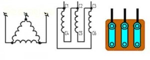
Therefore, in the design of a three-phase asynchronous motor, three windings are installed, located relative to each other at an angle of 120º. Each winding is connected to a phase circuit three-phase network AC. The windings are attached to the stator, which is a metal core in the form of a hollow body. They are also attached to the poles of the core.
Attention! Each winding has two free ends. One is connected to the network phase, the second to the other two ends of the other two windings, that is, into a single circuit.
The rotor is mounted inside the hollow core on bearings. Essentially, this is the same cylinder rod. Below is a diagram of the winding connection and the location of the rotor.
As soon as electric current begins to flow into the windings, a rotating magnetic field is formed, which acts on the rotor, causing it to rotate too.
How it works
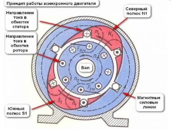
To understand the principle of operation of a three-phase asynchronous motor, it is necessary to consider its operating schedule. To make this task easier, we suggest considering the diagram below.
- So, position "A". In it, at the first pole the phase is zero, the second pole is north, that is, negative, in the third phase positive charge. Therefore, the current moves along the arrows indicated in the figure. For those who have forgotten their school physics curriculum, we remind you that the movement of the magnetic field operates according to the right-hand rule. This means that its rotation will be directed from north to south, that is, from the second coil (winding) to the third.
- Position "B". Now the zero is located on the second winding, on the first south (plus), on the third north (minus). That is, the magnetic flux will now be directed from coil No. 3 to coil No. 1. It turns out that the poles have shifted by 120º.
- In positions “B” and “G” exactly the same pole shifts of 120º occurred.
Reversing polarity creates rotation magnetic flux, which in turn drags the rotor along with it. The latter begins to rotate. As mentioned above, rotational (mechanical) energy is obtained from electrical energy.
Attention! If you swap the second and third windings, the rotation of the electric motor will begin in the opposite direction. Of course, the windings themselves are not rearranged, but simply the connection to different phases of the network is changed.
We examined the design of an asynchronous three-phase electric motor with three windings on the stator, which uses a two-pole magnetic field circuit. The number of its rotation revolutions is equal to the number of oscillations electric current per minute. If in an alternating current network the number of oscillations per second is 50 Hz, then in a minute this value will become 3000 (rpm).
But the stator can have more than three windings. For example, you can set six or ten. In this case, the magnetic field will become four-pole and six-pole, respectively. At the same time, the rotation speed of the rotor will also change. In the first case, it will be equal to: (50X60)/2=1500 rpm. In the second: (50X60)/3=1000 rpm.
We have already mentioned above that there is a certain lag between the rotation of the rotor and the rotation of the magnetic field. True, this value is insignificant. For example, in idle mode this figure will be only 3%, with active loads 5-7%. Even 7% is a small value, which is one of the advantages of an asynchronous motor.
How to use
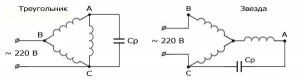
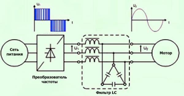
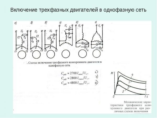
Unfortunately, not all private houses have three-phase voltage. Therefore, connecting a three-phase asynchronous motor to single-phase network produced through capacitors of a certain capacity. Usually the calculation is carried out in accordance with: for 1 kW of power 70 μF of capacitance. But there is another problem in this matter - the inability to regulate the speed of rotation of the rotor. Therefore, experts recommend connecting a speed controller for three-phase asynchronous motors to the motor.
- Firstly, by installing it, there is no need to install capacitors.
- Secondly, with the help of this device The power of the electric motor is equalized to the rated one.
- Thirdly, you can adjust the rotation speed and also increase it beyond the nominal value.
- Fourthly, you can adjust the starting torque.
These devices are sold today in specialized stores, but there is no problem making them yourself.
Rotor
According to the rotor design, asynchronous electric motors are divided into two groups:
- WITH wound rotor.
- Short-circuited.
The first option is engines with high power that require high starting torque. Slip rings are installed in their rotor design. The second option is a design in which copper rods are inserted into the grooves. These are typical electric motors, simple and cheap. But they have a couple of disadvantages: high starting current and weak force when starting to rotate.
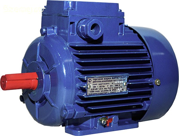
Specifications
What should you usually pay attention to when choosing electric motors? Technical characteristics, in principle, are few. This is power measured in kW, rotor speed in rpm. Everyone else technical specifications are not so important for selection. Although, for example, the mass of the product can help calculate the load on the stand or mounting frame.
Conclusion on the topic
So, we have considered asynchronous electric motors– electrical equipment, which is often used in private homes for domestic needs. The design and principle of operation of the motor is now clear to you, but how to properly connect the motor to a single-phase network, read in another article.
Related posts: 
Simplicity of production, low cost, and operational reliability have led to the fact that the asynchronous motor (IM) has become the most common electric motor. They can operate both from a three-phase electrical network and from a single-phase one.
Three-phase asynchronous motors are used:
In unregulated electric drives of pumps, fans, compressors, blowers, smoke exhausters, conveyors, automatic lines, forging machines, etc.:
In adjustable electric drives of metal-cutting machines, manipulators, robots, lifting mechanisms, general industrial mechanisms with variable productivity, etc.
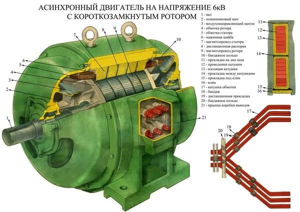
Design of three-phase asynchronous motor
Depending on the method of making the rotor winding of an asynchronous motor, the latter are divided into two groups: motors with a squirrel-cage winding on the rotor and motors with a phase winding on the rotor.
Motors with a squirrel-cage winding on the rotor are cheaper to manufacture, reliable in operation, and have a rigid mechanical characteristic, i.e., when the load changes from zero to the nominal speed, the machine rotation speed decreases by only 2-5%. The disadvantages of such engines include the difficulty of smoothly controlling the rotation speed over a wide range, a relatively small starting torque, as well as large starting currents, 5-7 times higher than the nominal one.
Motors with a wound rotor do not have these disadvantages, but their rotor design is much more complex, which leads to an increase in the cost of the motor as a whole. Therefore, they are used in the case of difficult starting conditions and when it is necessary to smoothly control the rotation speed over a wide range. The laboratory work examines an engine with a squirrel-cage rotor.
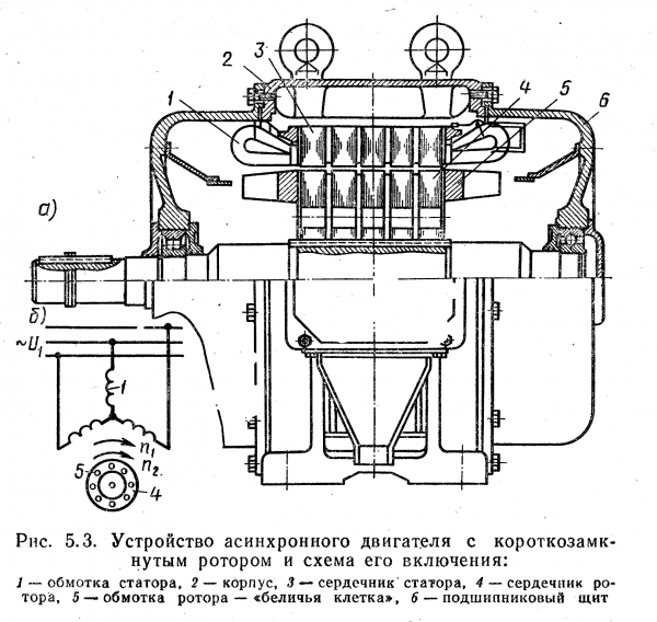
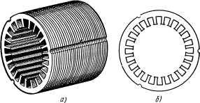
A three-phase asynchronous motor has a stationary part - stator 6 (Fig. 6.1), on which there is a winding that creates a rotating magnetic field, and a moving part - rotor 5 (Fig. 6.1), in which an electromagnetic torque is created, causing the rotor itself and the executive to rotate mechanism.
The stator core has the shape of a hollow cylinder (Fig. 6.2). To reduce energy losses from eddy currents, it is assembled from separate sheets of electrical steel, insulated from each other with a varnish film.
On the inner surface of the core there are grooves into which the stator winding fits. The core is pressed into the body (frame) 7 (Fig. 6.1), made of cast iron or aluminum alloy.
For a motor with one pair of poles, the stator winding is made of three identical coils, called phases. Each winding phase is placed in opposite slots of the stator core, the winding phases are shifted in space relative to each other by an angle and are connected to each other according to special rules. The beginnings and ends of the stator winding phases are connected to the output terminals of terminal box 4 (Fig. 6.1), which makes it possible to connect the stator winding phases with a star or triangle. In this regard, an asynchronous motor can be connected to a network with a linear voltage equal to Uph of the winding (the stator winding is connected by a triangle) or  Uф (the winding is connected by a star).
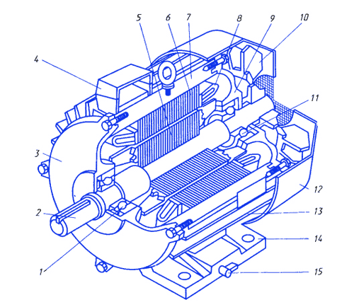
Rice. 6.1. - General view of the asynchronous motor:
bearings - 1 and 11, shaft - 2, bearing shields - 3 and 9, terminal box - 4, rotor - 5, stator - 6, frame - 7,
frontal parts of the stator phase winding - 8, fan - 10, cap - 12, fins - 13, feet - 14, grounding bolt - 15
R 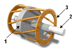 is. 6.2.
Rotor 5 (Fig. 6.1) consists of a core and a short-circuited winding. Rotor core 1 (Fig. 6.3) is assembled from sheets of electrical steel and mounted on shaft 2 (Fig. 6.3) of the engine; the sheets are insulated from each other by scale formed during the rolling process. The rotor sheets have grooves in which the windings are placed.
Motors with a squirrel-cage winding on the rotor have a number of designs based on the shape of the slots on the rotor. The shape of the rotor slots is selected depending on the requirements for the starting characteristics of the engine. The most rational for rotor slots with a short-circuited cage are trapezoidal oval slots. There are other modifications of the rotor grooves (bottle and trapezoidal profile).
The short-circuited rotor winding 3 (Fig. 6.3) is usually made of cast aluminum alloy. During the pouring process, both winding rods (conductors) located in the grooves and rings that short-circuit them, located outside the rotor core, are formed. The rings can be equipped with ventilation blades to improve engine ventilation and heat removal from the rotor winding. The absence of insulation of the rotor winding ensures good heat dissipation from the winding to the core. Such a short-circuited rotor winding, called a “squirrel cage”.
The shaft rotates in bearings mounted in side shields 3 and 9 (Fig. 6.1), called bearings. Bearing shields are attached to frame 7 (Fig. 6.1) using bolts.
There is an air gap between the rotor and stator of an asynchronous motor. When choosing an air gap, there are conflicting trends. Minimum air gap (selected for mechanical reasons) results in reduced current idle speed engine and increase power factor. However, with a small air gap, additional losses in the surface layer of the stator and rotor, additional torques and engine noise increase. As losses increase, efficiency decreases. Therefore, in modern series of asynchronous motors, the air gap is chosen to be slightly larger than required for mechanical reasons (so that the rotor does not touch the stator during operation).
The operating principle of an asynchronous motor is based on two phenomena: the formation of a rotating magnetic field by the stator winding currents and the effect of this field on the currents induced in the short-circuited turns of the rotor winding.
There are two types of three-phase electric motors, which differ in the design of the rotating part (rotor). The moving part of the engine is sometimes called the armature, but it would be more correct and professional to call it the rotor.
Asynchronous electric motors.
If an electric motor does not have a rotor with its own winding (voltage is not supplied to the rotor through the brushes), then it is a motor with a squirrel-cage rotor, or as I also call it an asynchronous motor. It is asynchronous because in this motor the rate of change of magnetic induction in the stator windings does not coincide (is not synchronous) with the speed of rotation of the rotor. Such three-phase motors are produced more, due to the simplicity of the design.
Electric motor with wound rotor.
A three-phase electric motor, in which the rotor has its own windings and voltage is supplied to these windings through brushes, is called a motor with a wound rotor. The complex design of such an electric motor is justified when it is necessary to regulate the rotation speed and it is necessary to reduce the starting currents of a powerful motor.
The stator (fixed part) of all three-phase electric motors is made identical in design. Structurally, windings made of copper winding wires are inserted into the stator magnetic circuit. The number of individual windings can be from 3, 6, 9-12. With three windings, the electric motor, when connected to the network, will rotate at a speed of 3000 rpm. per minute With six, nine, twelve windings, electric motors will rotate at speeds of 1500, 1000, 750 rpm, respectively. per minute, but with higher torques than a 3000 rpm engine. per minute
All given rotation speed values for individual motors are achieved only when connected to a three-phase network with a voltage of 380V, when the stator windings are connected in a star configuration.
Operating principle.
It's all about magnetic induction, which also makes useful work in electromagnets and transformers. Thanks to magnetic induction, metal objects are attracted to switched on electromagnets. Thanks to the same force, transformers transmit electricity from one coil to another, which are isolated from each other.
In electric motors, magnetic induction occurs when a non-contact connection is created between the stator and the rotor. In more detail, this happens as follows. Current passing through the stator windings of an electric motor creates a magnetic field. This field is not constant, as in an electromagnet or transformer. And quickly alternately changes its polarity, and returns to its initial state when it makes a revolution along the stator windings.
And the benefit of this electromagnetic field is that, thanks to the force of induction, it magnetizes a separate area on the surface of the rotor, parallel to the physical axis of the motor. And then, the alternating magnetic field pulls it along with it, thus forcing the stator to rotate around its axis.
Emergency operation mode (in case of phase failure).
Any break in the engine wires is an emergency that leads to damage to both the engine itself and the starting devices connected to it. The severity of the consequences of a phase failure depends on the circuit in which the motor windings are connected to the supply network.
When connecting the electric motor in a star configuration.
If the engine was running, the rotor will continue to rotate with a constant torque, but its rotation speed will noticeably decrease. In this case, in the remaining windings that remain connected to the voltage, an increased current will flow, equal in value in these two windings.
If you leave the motor running for a long time during a phase loss, the two connected windings will heat up evenly. Ultimately, an engine that is not maximally loaded and made with high quality can remain relatively intact. But the insulation resistance of the winding wires will decrease, as they will char when overheated. And the electric motor will no longer withstand such repeated torment.
When connecting the electric motor in a delta pattern.
If the engine was running, the rotor will continue to rotate, as in the previous case considered. But at the same time, in one of the remaining connected windings, the current will flow 1.73 times higher than during normal operation.
So, if you leave the motor running for a long time during a phase failure, one of the two connected windings will become very hot. And the engine itself will eventually smoke and stop. Because the enamel insulation on the winding wires inside the engine will collapse, and a short circuit will occur.
If you try to start an electric motor with a broken phase, it will either not start to rotate at all, or will pick up speed very slowly. And it doesn’t matter what circuit the engine is connected to. In this case, the engine will make a lot of noise due to the excessive magnetic flux that passes through part of the engine's magnetic circuit.
If two phases are broken, the running electric motor will stop, the idle motor will not start, and there will be no harmful consequences.
Connection to a single-phase network.
Very often there is a need to use three phase motor instead of single-phase washing machine, fan, various woodworking machines, water pumps, grinding machines.
Most often, electric motors are connected in a star configuration, since in this case they can be used in a three-phase network, that is, with a maximum operating voltage of 380V. But when connected to a single-phase network, at a reduced voltage of 220V, such a scheme is not suitable at all. Because an electric motor connected in a star configuration to a single-phase network will lose half of its power.
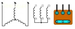
Specifically, a star connection is when the ends of three windings are twisted together, and the beginnings of these windings are connected to the mains supply.
This is how the wires are connected to the terminal block and how you need to place the jumpers in distribution box(born) electric motor when connected in a star configuration.
According to the "triangle" pattern.
If you need to connect a three-phase electric motor to a single-phase network with a voltage of 220V, then it is advisable to assemble the windings in a triangle pattern. Because, with such a switching scheme, the engine will lose only 30% of its rated power. And besides, the rotation speed will not decrease at all.
In general, to make a delta connection, you need to connect the end of one winding to the beginning of another, and so connect all the windings in series, and connect their connection points to the power supply network.
This is how the wires should be connected to the terminal block, and this is how the jumpers are located in the electric motor when connected in a triangle.
Be careful! There are three-phase electric motors designed for operating voltages of 220/127V. And if you switch such a motor to a “delta” circuit in the burner, that is, to a reduced voltage of 127V, and then connect it to a single-phase network of standard voltage 220V, then the motor will quickly burn out.
In order for a three-phase electric motor to operate in a single-phase network, a phase-shifting capacitor, or as it is also called, a working capacitor, will also be needed.
Ultimately, you need to connect the ends of the phase-shifting capacitor to two terminals in the born, and connect two wires from the network like this: one to any terminal of the capacitor; the second to the free terminal in the bourne.