Frequency of operational tests of electrical installations. Measurements and tests when setting up electrical equipment - setting up electrical installations
Page 3 of 19
TYPES OF TESTS FOR ELECTRICAL EQUIPMENT
During the installation process and after its completion, as well as under operating conditions, the electrical equipment of electrical installations undergoes inspection, testing and adjustment.
Electrical equipment may be damaged during transportation and installation. During operation, it may be damaged due to natural wear and tear, as well as design defects.
The adjustment of electrical equipment is subject to regulated requirements, to comply with which the following tests are carried out:
standard in accordance with current GOSTs;
acceptance and delivery in accordance with the PUE, and in some cases with the instructions of the Ministry of Energy;
preventive and others in accordance with the Rules technical operation electrical stations and networks (PTE), the scope and standards of testing of electrical equipment and instructions for individual elements of electrical equipment.
Type tests are carried out at manufacturing plants according to the programs and with the volumes specified in the standards and technical conditions, but some of them can be carried out at the installation site of electrical installations. During type tests, the compliance of electrical equipment with the requirements imposed on it by standards is checked.
Acceptance tests are carried out in newly constructed and reconstructed installations up to 500 kV.
During testing, the compliance of the installed equipment with the design is determined, the necessary characteristics are taken and a certain amount of measurements are performed. After reviewing the test results, a conclusion is made on the suitability of the equipment for operation.
Preventive tests are carried out during equipment operation, which allows expanding the possibilities of detecting defects for the purpose of timely repair or replacement of equipment.
MEASUREMENT OF RESISTANCE AND INSULATION RESISTANCE
Measuring the resistance of resistors is included in the scope of almost all types of commissioning and operational work. When performing these measurements, the integrity of the current-carrying circuits of electrical machines and devices is revealed, breaks in coils, parallel branches, turn short circuits are detected, the quality of welding, soldering, etc. is checked.
Rice. I Connection circuits for instruments for measuring resistance using the ammeter and voltmeter method:
a - small, b - large, c - very small, S - switch, GB - battery, RK - rheostat, PA - ammeter, Xi - Xa - clamps
For measuring resistance DC use a variety of instruments and the following methods: ammeter - voltmeter, electric bridge, microohmmeter.
The ammeter and voltmeter method is used in all cases where particularly high measurement accuracy is not required. This method is convenient to use when measuring resistances in operating mode. The measurement accuracy is determined by the sum of the errors of the ammeter and voltmeter. To obtain sufficiently accurate results, it is necessary to use instruments of accuracy class 0.5 with an error of no more than 0.5%. The measurement limits of instruments are chosen so that readings are taken in the second half of their scale. Typically, in such cases, multi-range voltmeters are used with limits for measuring voltage in DC circuits from 0.045 to 300 V and current from 0.03 to 30 A. The method is based on Ohm's law, according to which the measured resistance of any conductor R is equal to the voltage at its terminals U divided by the current passing through the conductor /:R = z=U/l. Thus, if you pass current through a resistance and measure it and the voltage at the terminals of the resistance, you can determine the value of the resistance.
There are two possible circuits for connecting a voltmeter and an ammeter to measure resistance, shown in Fig. 1, a, b. When measuring very small resistances, a millivoltmeter PV is used, which, in order to avoid errors from the resistance of the connecting wires and transition contacts, is connected to the potential terminals of the measured resistance Xi - /V3 (Fig. 1, c).
The ammeter and voltmeter method gives correct results if the following conditions are met:
the number of detachable contacts in the measurement circuit should be minimal;
The source of direct current must be a network or a battery of sufficient capacity with a voltage of 4-12 V; 
Fig 2 DC measuring bridge circuit
readings from both instruments must be carried out simultaneously by two persons at the command of one of them;
resistance should be measured at different meanings current;
When making high-precision measurements, you must choose devices of a class of at least 0.5.
Electric bridges are used to measure resistance (10-8-10+16 Ohms) to direct current with high accuracy.
The measuring bridge, shown in Fig. 2, consists of three resistors R1, R2, Rc, which, together with the measured resistance of the resistor Rm, form a quadrilateral ABCD. Its diagonals include batteries GB and a galvanometer P (a sensitive magnetoelectric device).
In Fig. 3, a, b are shown general view and a diagram of the MMV rheochord bridge. Bridges in which the resistance in the arms is made in the form of calibrated manganin wire are called rheochord. The rheochord is divided by contact D sliding along it into two arms. To measure the resistance Rk of the resistor Rx, it is enough to know the ratio of resistances R1/R2, therefore, on the scale of the sliding contact, not the values of the resistances Ri and Rg, but the values of their ratios at different positions of the slider are plotted. On the scale of the resistance switch in the comparison arm r3, resistance values from 0.1 are plotted up to 1000 Ohm.
To determine the unknown resistance Rgh, it is connected to terminals / and 2, first setting the expected value of the unknown resistance in the comparison arm R3. Then press button 5 (S) and rotate the rotor handle 3 until the galvanometer needle is set to zero. The measured resistance is equal to the product of readings on the slider scale 3 and the switch handle of 4 measurement ranges.
The MMV bridge is a resistance indicator and is intended for technical resistance measurements. The indicator's power source is a 3336 battery. When measuring resistances less than i Ohm, the resistance of the connecting conductors is taken into account.
For more accurate resistance measurements in the practice of adjustment work, DC bridges R 316, UMV, RZZZ are widely used.
To measure small resistances, a microohmmeter is used, which gives an effect for a large number of measurements, for example: transition resistances busbar contacts, oil switches, resistances between adjacent pairs of collector plates of electrical machines and other electrical equipment. 
Rice. 3. Small bridge - a - general view, b - diagram
During adjustment work, microohmmeters F415, F4104 are used.
Insulation resistance of electrical circuits, machines and devices - the most important indicator state of the electrical installation.
This resistance is measured using a megohmmeter, given that its value largely depends on the time after which the reading is made. Therefore, the measured insulation resistance is taken to be the steady-state value that occurs 1 minute after the voltage is applied. Measurements must be carried out in accordance with current safety regulations by persons with the required qualification group.
When assessing the state of insulation resistance, the absorption method is used. In this case, the megohmmeter readings obtained 15 and 60 s after applying voltage to the insulation are compared. The ratio (absorption coefficient) is taken as an indicator for comparison
Kza = R60/R15,
where R60 and R15 are insulation resistances, measured 60 and 15 s after applying voltage to the insulation.
The absorption coefficient value is compared with previous measurements. During adjustment work, measurements of this coefficient are performed at a positive temperature (not lower than 10 °C). At 15-30 °C for unmoistened windings it is in the range of 1.3-2. Humidified windings have an absorption coefficient close to unity.
Before starting measurements, in order to avoid errors, the following measures must be taken: remove dust, clean insulators, eliminate dampness. The measurement is carried out with a 1000 or 2500 V megohmmeter.
When performing adjustment work, megohmmeters are widely used various types and voltages (at 100, 500, 1000 and 2500 V). Diagrams of megaohmmeters are shown in Fig. 4. Megaohmmeter M4100/1-4 (Fig. 4, a) consists of a measuring mechanism P with a scale graduated in ohms or megaohms, a rectifier UD and a generator G constant or AC followed by rectification, resistors Rl - R4 and capacitors Cl, C2. The conversion of alternating current to direct current is necessary because during testing the instrument readings would depend not only on the measured insulation resistance, but also on the capacitance of the circuit under test, especially for cable and air lines having a large capacity.

Rice. 4. Megger circuits: a - M4100/1-4. 5 - M4100/ 5
The measuring mechanism is made in the form of a two-frame magnetoelectric ratiometer. The measured resistance is connected between terminals L (line) and 3 (ground) and the generator armature handle is rotated by hand. The current generated by the generator passes through two parallel branches. One part of the current flows from the rectifier UD through the resistances of resistors Rl, R2 and one of the windings of the measuring mechanism. The value of this current does not depend on the value of the measured resistance. The other part of the current flows through the second winding of the measuring mechanism, the measured insulation resistance and the resistance of resistors R3, R4. Consequently, the value of the current in this winding depends on the value of the measured resistance. Thus, the deflection of the arrow of the measuring mechanism depends on the ratio of currents in its windings. Therefore, at a constant voltage developed by the generator, the deflection of the needle of the measuring mechanism depends only on the value of the measured resistance, which makes it possible to directly plot Ohms (or mega-ohms and kilo-ohms) on the scale.
The generator armature reaches the rated frequency when the device handle is rotated at a frequency of 120 rpm. A centrifugal regulator is placed on the armature shaft, ensuring constant voltage when the armature rotation speed increases above the nominal one. In Fig. 4, 6 shows the electrical circuit of the M4100/5 megohmmeter for 2500 V, which differs in design from the M4100/1-4 megohmmeter in the number of capacitors and a rectifier assembled according to the voltage multiplication circuit.

Rice. 5. Schemes for measuring insulation resistance with megohmmeters: a - M4100/I-4 at the limit, b - M4100/1 - 4 ka at the limit "ky", c - M4 100/5 at the limit
"MY", g - M4100/5 at the limit "ky"
To eliminate the influence of surface leakage currents, which can distort the results of measuring insulation resistance, the circuits of some devices provide a special third terminal E (screen), which is connected directly to the generator terminal (Fig. 4.6). In this case, the currents along the surface of the moistened insulator are diverted to the ground, bypassing the windings of the measuring mechanism. Line terminal L is protected by a protective insulating ring. Schemes for measuring insulation resistance with megaohmmeters M4100/1-5 are shown in Fig. 5, a - d. When measuring at the kQ limit, a jumper on one of the complete connecting wires is connected to terminals L - 3, and the measured resistance is between terminals 3 - /it.
Technical characteristics of megaohmmeters M4100/1-5 are given in table. 1.
Before taking measurements, you need to make sure that the megohmmeter is working properly. When rotating the generator knob, the indicator arrow should be set to the “c” mark on the MOhm scale, and when installing the jumper between terminals L - 3 - to “0” of the same scale. Otherwise, the device is considered faulty.
Table I. Technical characteristics of megaohmmeters M 4100/1-5
Modifica tion |
Limits |
Working part scales |
Nominal |
Basic error, % of the length of the working scale |
||
Note. The technical indicators and diagrams of megaohmmeters of the latest releases have minor changes.
It is forbidden to start measurements without making sure that there is no voltage on the object being tested!
Rice. 6. Connection diagram for megaohmmeter M4I00/5
Depending on the resistance being measured, the connection is made to the appropriate terminals, for example for megaohmmeters M 4100/5 as shown in Fig. 6.
Measurements with a megohmmeter are carried out by two people: one rotates the generator handle, the other touches the parts of the circuit to be measured. The countdown is made after the arrow reaches a stable position.
When measuring the insulation of high-voltage equipment, you should use a 2500 V megohmmeter, and when measuring low-voltage equipment - 100, 500 and 1000 V.
When checking the insulation of electrical equipment, make sure not to apply increased voltage to parts and elements of electrical installations with a reduced test voltage (capacitors, rectifiers, microcircuits, etc.).
Before putting an electrical installation or electrical equipment into operation, it is necessary to carry out control tests of the electrical installation, which make it possible to identify possible defects. In addition to detecting defects during routine inspections, it is possible to obtain data that is necessary for carrying out preventive inspections and for checking the compliance of installations or equipment with their specifications. technical specifications and standards prescribed in technical regulations approved at the legislative level. Control tests of the electrical installation must be carried out by specialists from an electrical measuring laboratory that has a certificate of registration with Rostekhnadzor.
Control tests of the electrical installation by our electrical laboratory.
Our company has repeatedly carried out control tests of electrical installations and has precise measuring equipment and uses modern techniques in its work. This allows our specialists to carry out control tests of electrical installations efficiently and quickly. When our electrical measuring laboratory detects faults and defects, we help control the process and quality of their elimination.
There are certain requirements when conducting control tests. These requirements are specified in the PUE and PTEEP. Among the requirements, it is worth talking separately about established deadlines such tests, since there is an obligation for organizations to conduct control tests of all existing electrical equipment at certain intervals. For example, electrical networks located in special hazardous areas, is carried out at least once a year. Other cases require such tests to be carried out once every 3 years. Elevator equipment and cranes must be inspected annually. Electric stoves are subject to control tests only in a heated state and at least once a year. For other electrical installations and electrical equipment, control tests are carried out within the time limits established by the technical manager of the Consumer. depend on the type of equipment being examined.
Control tests of electrical installations are the basis for operational safety.
The safety and reliability of electrical installations and equipment directly depends not only on compliance with technical requirements and standards, but also on regular inspection. Due to the existence of strict requirements imposed by supervisory authorities, the safest operation of the facility is ensured. To ensure people are protected from injury electric shock, safety of the equipment itself and ensuring fire safety at the facility itself, control tests of insulating materials of current-carrying elements and equipment components should also be regularly carried out.
Today, electrical equipment testing is one of the important parts of inspection modern production- industrial facility.
The frequency of testing electrical equipment depends on the power of the device, its features, purpose, and level of wear during operation. In most cases, the frequency is set depending on the power - the more powerful the device, the more often it needs to be checked for operability and absence of breakdowns.
Electrical equipment testing, which occurs every few years, includes the whole complex activities, several tests, each of which is designed to check one or a group of parameters.
Types of electrical equipment inspections
Modern types of electrical equipment testing include:
- checking the temperature regime, compliance of real indicators with maximum permissible standards;
- checking for breakdowns or malfunctions;
- high voltage testing, which can be used to identify even minor defects, which only in the future can develop into major breakdowns;
- checks may differ in other parameters.
Other parameters include a check that is carried out in connection with the device undergoing repairs, or during the first start-up (commissioning).
The electrical testing program may vary significantly depending on the type of test itself. For example, checking the insulation integrity does not imply any work other than testing the device in this area.
At the same time, testing and inspection using a thermal imager will allow you to detect defects both in the device itself and in the cables connected to it.
Tests and measurements of electrical equipment vary, so if the owner begins to doubt the serviceability of his device, he should determine the type of failure in order to order the necessary tests. But in most cases, specialists called to the site are themselves able to determine what kind of breakdown there may be and what method it can be installed and identified.
Testing times for electrical equipment
In terms of speed, electrical testing times vary depending on the type of device being tested and the test method chosen. For example, measurements taken during a malfunction take longer than regular, scheduled, periodic ones.
The time frame for checking electrical equipment at an enterprise is usually very tight, since the inspectors themselves have a good idea of what the downtime of an industrial facility threatens, and that is why specialists try to complete their work as quickly as possible.
Who to contact for quality testing of electrical equipment
If you need to find people who offer to carry out preventive testing of electrical equipment up to 1000 V or higher, then you should contact specialized companies for which the provision of such services is their main focus. But before you turn to a company for a service, you should make sure that it has the right to perform such checks.
If a logical question arises - who grants permission to test electrical equipment, then the easiest way is to request the relevant documents from the testing company itself. The potential customer must be presented with permits from Rostechnadzor, as well as employee certificates of professional certification.
If there are no such documents, then any operational tests of electrical equipment, as well as preventive ones, will be considered invalid, and the results of such a test will not be taken into account by government agencies. Consequently, the owner of the equipment will have to look for a new contractor who can carry out the inspection, this time issuing the necessary documents.
"StandardService" has all permissions to provide such services. These include preventive and regular testing of electrical equipment.
We offer inter-repair testing of electrical equipment, and can also carry out direct repairs, having previously identified faults.
We offer our customers high-voltage testing of electrical equipment, testing, and much more.
At the same time, we offer our services for affordable prices, we promptly go to sites, carry out testing, inspections and tests in a compressed, record-breaking manner short terms, without loss of quality.
It will be convenient for the customer that it is from us, in one company, that you can order inspection and testing of equipment and installations, check the enterprise network, and conduct cable tests.
Our specialists offer their services to both business owners and owners of private, country, or apartment buildings.
Page 14 of 14
§ 9. Terms and standards for testing electrical equipment
Every phase electrical wires, busbars, cables, windings and contacts of electrical devices must be carefully insulated from one another and from grounding structures. However, over time, during the operation of electrical equipment, the dielectric characteristics of the insulation change. The aging of insulation is affected by the heating temperature of the conductors and the outside air, room humidity, switching overvoltages that occur in electrical circuits with inductive and capacitive elements, duration of operation, etc. Such insulation sometimes does not withstand even rated voltages, as a result of which electrical breakdown occurs.
Therefore, in order to ensure that electrical equipment and devices do not fail due to the fact that their insulation resistance is below the permissible standard, and also that electrical networks no short circuits occurred due to electrical breakdowns of insulation; all types of insulation are checked and tested within certain periods in accordance with the “Rules for the technical operation of power plants and networks.”
These tests are carried out, as a rule, at current and major repairs electrical equipment. In addition, between-repairs, i.e., preventive tests are carried out, which make it possible to identify problems arising during the installation or operation of equipment or cable lines defects, which makes it possible to eliminate these defects in a timely manner, prevent an accident or prevent a reduction in the supply of electricity to consumers.
For each equipment, devices and networks, there are insulation resistance standards, which are established by the “Rules for Electrical Installations”.
To determine the condition of the insulation, two methods are used: measuring the resistance of a given section of an electrical installation or apparatus using a megohmmeter or checking the condition of the insulation with an increased, strictly standardized voltage.
Rice. 46. Megaohmmeter:
A- general view, b- simplified diagram: 1
- frame, 2
- inductor
When measuring insulation resistance with a megaohmmeter (Fig. 46), the arrow on its scale shows the insulation resistance of the device or section or circuit being tested. Framework 1
magnetoelectric system is powered by current from an inductor 2
, rotated by hand. When the clamps X1 And X2 open, current passes only through the frame with the additional resistor R2 and the moving part of the magnetoelectric system is installed in one of its extreme positions with the sign , which indicates an infinitely large resistance. If you close the clamps X1 And X2, the current will flow through the second frame with an additional resistor R1. In this case, the moving system will be installed in another extreme position, marked “0” on the scale, i.e., the measured resistance will be zero. When connecting the measured resistance Rx to the clamps X1 And X2 the moving system will be installed in an intermediate position between and 0 and the arrow on the scale will indicate the value of this resistance. The megohmmeter scale is calibrated in kiloohms and megohms: 1 kOhm = 1000 Ohms; 1 MΩ = 1000 kΩ. Inductor DC generators with manual drive from a handle are used as a source of direct current in megaohmmegrs.
The voltage at the external terminals of the generator depends on the speed of rotation of the handle. To smooth out oscillations during rotation, a centrifugal regulator is built into the drive.
Rated frequency rotation of the megohmmeter generator is 2 rpm or 120 rpm.
To connect the megohmmeter, use PVL connecting wires with moisture-resistant insulation, otherwise the megohmmeter readings may be significantly distorted.
Megaohmmeters are produced with rated terminal voltages: Ml 101M - 500 and 1000 V, MS-05 - 2500 V.
When measuring the insulation resistance of long cable lines and windings of electrical machines and transformers, the megohmmeter readings at the beginning of rotation of the handle decrease sharply. This is explained by the presence of significant capacity in cable lines and electrical machines through which the charging current passes. Therefore, in such cases, when using a megohmmeter to measure insulation resistance, the device readings are taken only after 60 s. from the moment the handle begins to rotate.
Touching the circuit being measured while rotating the handle of a megohmmeter connected to the circuit is dangerous and may result in electric shock. Therefore, when taking measurements, the necessary safety measures are taken to prevent people from touching electrical circuits.
In installations large capacity(long cable lines, transformers high power) the measured circuit can acquire significant electric charge. Therefore, after removing the voltage from the megohmmeter, such circuits are discharged using a flexible copper wire to the ground using an insulating rod to connect to each of its phases. In installations with voltages above 1000 V, cables and large machines are discharged in dielectric gloves and galoshes.
To test insulation with increased voltage, various rectified and alternating current devices are used.
Most often, when testing insulation, a kenotron installation is used, circuit diagram which is shown in Fig. 47, a. It is mounted in the body of a car and has own source electricity. The positive pole of the kenotron lamp (anode) is grounded, and the negative pole (cathode) is connected to one of the phases of the electrical installation under test (for example, a cable), while the other two phases and the shell are grounded (Fig. 47, b).
Kenotron insulation tester KII-70 is a unit consisting of a mobile control panel and a kenotron attachment. It is designed for testing solid liquid dielectrics with DC voltages up to 70 kV. The test voltage is changed from 0 to 70 kV using a regulator with an additional winding to power the signal lamp circuit.
The kenotron attachment consists of a transformer and a kenotron placed in a bakelite cylinder filled with transformer oil. At the top of the console there is a three-limit microammeter with a scale of 200, 1000 and 5000 μA and a limit switch designed to measure leakage currents. The set-top box has terminals for connecting DC circuits high voltage and the test object. In addition, the device is equipped with an overcurrent protection device with two settings: coarse and sensitive. 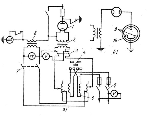
Rice. 47. Schemes of kenotron installation:
A- principled, b- testing cables with lead sheath; 1
- kenotron lamp, 2
- filament transformer, 3
- heat switch, 4
- power switch, 5
- power switch, 6
- control transformer, 7
- contactor, 8
- test transformer, 9
- cable cores, 10
- cable sheath
on the higher voltage side of the tester, while it does not operate in the minute power mode at a voltage of 50 kV.
A sensitive setting switches off the device when short circuit on the high voltage side of the transformer. In this case, the protection should not operate at a voltage of 70 kV and a secondary current of 5 mA.
On the cover of the tester's control panel there is a maximum current protection device, a maximum protection switch, a signal lamp, and a kilovoltmeter.
For direct current testing, the kenotron attachment is installed on the hinged door of the control panel and the tested object is connected to it. Using a regulator, voltage is supplied to the control panel, gradually increasing it to the test value. The voltage is controlled on the scale of the device, calibrated in kilovolts (maximum). At the last minute of the test time, the leakage current is measured using a microammeter.
Testing with alternating current of industrial frequency is carried out by connecting the test object to the alternating current terminal, after which the voltage is raised by the regulator to the test voltage. Voltage control is carried out on a kilovoltmeter scale, calibrated in kilovolts.
During testing, the voltage is gradually raised to the test voltage and maintained unchanged throughout the entire test period. The test time is determined by the “Rules for the technical operation of consumer electrical installations and safety rules for the operation of consumer electrical installations” for each type of equipment, apparatus and networks and ranges from 1 to 10 minutes.
During the overhaul of switchgears with voltages up to 1 kV, which is carried out once every 3 years, the insulation resistance of drive elements of switches, disconnectors, secondary circuits of equipment, power and lighting wiring is tested with an industrial frequency voltage of 1 kV for 1 minute or with a megohmmeter with a voltage of 1000 V . When measuring insulation resistance in power circuits Electrical receivers, devices and devices must be turned off, and in lighting networks, lamps must be turned out, sockets, switches, and group panels from electrical receivers must be disconnected.
The lowest permissible values of insulation resistance of secondary control circuits, protection, alarm relay circuits, power and lighting wiring, switchgears, switchboards and conductors with voltages up to 1000 V are 0.5 MOhm, and operational current buses and voltage circuit buses on the control panel - 10 MOhm.
An increased voltage of 1000 V is tested for 1 min. secondary circuits protection, control, alarm circuits with all connected devices (drive coils, automatic machines, magnetic starters, contactors, relays, etc.). The insulation resistance of the battery after its installation must be no less than:
Measurement of loads and voltage at control points of the lighting network is carried out once a year; The insulation resistance of portable transformers with a secondary voltage of 12 - 42 V is tested once every 3 months, and stationary ones - once a year.
Switches, disconnectors, grounding blades, short circuiters, separators and their drives are tested at least once every 3 years, simultaneously with major repairs. The lowest permissible resistance values of the supporting insulation, measured with a megohmmeter for a voltage of 2.5 kV, at rated voltage up to 15 kV are 1000 MOhm and over 20 kV - 5000 MOhm. Testing of this insulation of switches with voltages up to 35 kV with increased voltage of industrial frequency is carried out within 1 minute. At the same time, the contact resistance to direct current is measured, which is for: VMG-133 (1000 A) - 75 μOhm; VMP-10 (1000 A) - 40 μOhm; VMP-10 (1500 A) - 30 μOhm; VMP-10 (600 A) - 55 μOhm.
The insulation resistance of suspended and multi-element insulators is measured with a megohmmeter for a voltage of 2.5 kV only at positive ambient temperatures, and the insulation resistance of each suspended insulator or element of a pin insulator must be at least 300 MOhm.
Testing with increased power frequency voltage of newly installed multi-element support and suspension insulators is carried out with a voltage of 50 kV. Each element of a ceramic insulator is tested for 1 minute, of organic material - 5 minutes. Support single-element insulators of indoor and outdoor installations are tested at the increased voltage indicated in table. 24, for 1 min.
Table 4. Test voltage of support single-element insulators, kV
Pin insulators of bus bridges with a voltage of 6 - 10 kV, support and suspension porcelain disc insulators, as well as contact connections of busbars and connections to equipment in the absence of temperature indicators are tested once every 3 years. Testing the insulation resistance of bushings and bushings is carried out with a megohmmeter at a voltage of 1000 - 2500 V for bushings with paper-oil insulation. The insulation resistance must be at least 1000 MOhm. Insulators of bushings and bushings with voltages up to 35 kV are tested with increased voltage, the value of which is indicated in table. 5.
Measuring the insulation resistance of moving and guiding parts made of organic materials, oil switches of all voltage classes are made with a megohmmeter for a voltage of 2500 V. Moreover, the lowest permissible insulation resistance must be no less than: for voltages up to 10 kV - 1000 MOhm, from 15 to 150 kV - 3000 MOhm.
Table 5. Test voltage of bushings and bushings
Testing the insulation of oil switches with voltages up to 35 kV at high power frequency voltage is carried out within 1 minute. The test voltage is taken in accordance with the data in table. 6.
Table 6. Test voltage of external insulation of oil switches
The DC resistance of oil switch contacts should not differ from the manufacturer's data.
When testing oil switches, their speed and time characteristics are also subject to verification. These measurements are made for switches of all voltage classes. The measured characteristics must correspond to the manufacturer's data.
After repair, winding insulation power transformers together with the inputs, they are subjected to tests with increased alternating current voltage with an industrial frequency of 50 Hz. The test voltage depends on the type of repair and the scope of work (with or without changing the transformer windings).
The insulation of each winding, not electrically connected to the other, is tested separately.
The test voltage values at an industrial current frequency of 50 Hz are indicated in table. 7.
Table 7. Test voltage of insulation of windings together with inputs, kV
The test results are recorded in the protocol. This data is necessary to compare the results obtained with the results of previous tests carried out at various times before this repair.
Tests of transformers after repair are carried out throughout the entire program and to the extent provided for by the current rules and regulations.
During preventive tests, the insulation of power transformer windings is tested with increased power frequency voltage in accordance with Table. 8 for 1 min.
Table 8. Test voltages of internal insulation of oil-filled transformers
The DC winding resistance is measured on all branches and may differ by no more than 2% from the manufacturer's data.
The transformation ratio of the transformer is checked at all switching stages. Permissible deviations can be no more than 2% from the values obtained on the same branch on other phases, or from the manufacturer's data.
The minimum breakdown voltage of the oil, determined in a standard vessel before pouring into transformers and insulators, for voltages up to 15 kV should be 30 kV, and from 15 to 35 kV - 35 kV.
For fresh oil, before filling a newly commissioned transformer, a complete chemical analysis is carried out according to a special program.
Measurement of the insulation resistance of leads and rods made of organic materials is carried out with a megohmmeter for a voltage of 2500 V. The lowest permissible insulation resistance of organic materials at a rated voltage of up to 10 kV should be 1000 MOhm, at a voltage from 15 to 150 kV - 3000 MOhm.
Insulation resistance measurement primary windings measuring transformers are made with a megohmmeter for a voltage of 2500 V, and for secondary windings - for 500 or 1000 V. The insulation resistance of the primary winding is not standardized, but the resistance secondary winding together with the circuits connected to it must be at least 1 MOhm.
Depending on the insulation resistance of the primary windings of current and voltage transformers up to 35 kV, the test is carried out at the following test voltage values. If the insulation resistance is designed for a voltage of 6 kV, the test voltage is taken equal to 28.8 kV, for a voltage of 10 kV - 37.8 kV, for a voltage of 20 kV - 58.5 kV.
The duration of application of the test voltage for the primary windings of instrument transformers is 1 min. Only for current transformers with insulation made of hard ceramic materials or cable masses, the duration of application of the test voltage is 5 minutes.
For dry reactors, the insulation resistance of the windings relative to the fastening bolts is measured with a megohmmeter for a voltage of 1000 - 2500 V. Its value must be at least 0.5 MOhm.
Porcelain insulation of the reactor, as well as fuses above 1000 V, is tested with increased power frequency voltage for 1 minute with the following test voltage values: at a rated voltage of 6 kV - 32 kV, at 10 kV - 42 kV, at 20 kV - 65 kV.
The insulation resistance of power cable lines is measured with a megohmmeter for a voltage of 2500 V. In Fig. Figure 48 shows a diagram for connecting a megohmmeter when measuring cable resistance. For power cable lines with voltages up to 1000 V, the insulation resistance must be at least 0.5 MOhm, and for voltages above 1000 V, the insulation resistance is not standardized. Measurements with a megohmmeter should be made before and after testing the cable with increased voltage. Power cables voltages above 1000 V are tested with increased rectified current voltage.
Test voltages and the duration of their application are given in table. 9.
Data from all tests and measurements are recorded in the electrical equipment test log and in test and measurement reports.
Table 9. Rectified current test voltages for power cables
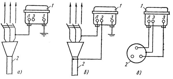
Rice. 48. Diagram for connecting a megohmmeter when measuring cable resistance
A- circuit for measuring insulation relative to ground, b- circuit in the presence of surface leakage currents, V- measurement of insulation between cores, 1 2 - cable
This data is used for comparison in subsequent tests and measurements. They make it possible to analyze the condition and performance of equipment, plan the time for necessary repairs to increase insulation resistance or reduce leakage currents, and thus increase the time of equipment operation in trouble-free mode.
Electrical equipment is regularly tested, which pursue the goals of checking compliance with established technical characteristics, obtaining data for carrying out the following preventive tests, establishing the absence of defects, as well as studying the operation of electrical equipment. The following types of tests are distinguished: operational, acceptance, control, standard, special.
Type tests are used for new equipment, which differs from old models in its updated design and device. This type of testing is carried out by the manufacturer in order to verify compliance with all requirements and standards that apply to this type of equipment or technical conditions.
To check the compliance of the manufactured product with all the main technical requirements Each product is subjected to control tests (device, machine, instrument, etc.). To carry out control tests, as a rule, a reduced work program is used (compared to standard ones).
Acceptance tests used after completion of installation of newly commissioned equipment in order to assess its suitability for operation.
Performance tests are carried out for equipment in operation, including those that have undergone repair. This type of test is used to determine the serviceability of the equipment. Operational tests include tests during current and major repairs, as well as preventive tests that are not related to the removal of equipment for repair.
For research purposes or other special programs Special tests may be carried out.
Some of the testing work is carried out similarly for almost all elements of electrical equipment. These types of work include: testing and checking insulation, monitoring electrical connection diagrams.
When checking electrical connection diagrams, the following actions are carried out:
1) familiarization with technical information on the facility - installation and fundamental (complete) switching diagrams, cable log are studied;
2) checking for compliance with the design of real equipment and equipment;
3) checking and inspecting the compliance of cables and wires (section, material, brand, etc.) with the current rules and design;
4) control of the correctness and presence of markings on cable cores and wires, device terminals, terminal blocks;
5) quality control of installation (cable laying, cable laying on panels, reliability of contact connections, etc.);
6) continuity testing (monitoring the correct installation of circuits);
7) reliability test electrical diagrams when submitting .
The most complete tests in the primary and secondary switching circuits are carried out during acceptance tests after completion of installation of electrical equipment. During maintenance tests, the number of switching control operations is significantly reduced. Installers or adjusters must eliminate deviations from the design or installation errors discovered during the inspection. In order to change or deviate from the project, it is necessary to first obtain the consent of the design organization. Any such changes must be provided in the form of drawings.