Railway contact network. What is the voltage in the suburban train wire
Top news:
»
New railway lines are being built to develop new regions and their natural resources, to unload busy existing lines, to shorten the route and time for passengers and cargo. New lines may differ significantly in their significance, size and nature of traffic. Depending on these factors, the technical requirements and standards that guide the development of pro...
»
Under the action of forces that are created when trains move along rails, and especially when braking on long descents, there can be a longitudinal movement of the rails along the sleepers or together with the sleepers along the ballast, called track theft. On double-track sections, hijacking occurs in the direction of travel, and on single-track lines, hijacking is two-way.
»
Intermediate stations are separate points that have a track development for overtaking, crossing and passing trains, as well as loading and unloading goods. Thus, these stations differ from sidings and passing points in the presence of devices for cargo operations. Intermediate stations are placed on the line in such a way as to ensure the throughput of the section and meet the needs ...
»
The movement schedule is characterized by quantitative and qualitative indicators. Quantitative indicators include: the number of freight and passenger trains plotted on the schedule, the dimensions of loading and unloading that can be mastered with this schedule, etc. The main qualitative indicators of the schedule include: technical, sectional and block speeds (separately for freight and passenger trains ) ...
»
On June 17, in Vologda, the head of the Northern Railway, Vasily Bilokha, presented the head of the Vologda branch, Sergei Almeev, and the chairman of the territorial committee of the trade union, Valentin Yakk, with a certificate of first place in the industry competition for the 1st quarter of 2009. To achieve such success, the staff of the department completed everything in the 1st quarter planned performance...
»
The northern branch of the NPF "BLAGOSOSTOYANIE" held a seminar-meeting with personnel employees of the structural divisions of the Yaroslavl and Vologda branches, directorates and subsidiaries and affiliates on topical issues of non-state pension provision. Attracting employees of the North to participate in non-state pension provision is still an urgent area of work for personnel officers, noted Natalia Zh...
»
The rolling stock of subways consists of all-metal motor cars of types G, D, E. A traction engine is installed on each axle of the motor car. The cars are equipped with current collectors for the lower current collection from the contact rail installed to the left of the running rail. Braking in cars is automatic. They are equipped with pneumatic, electric and, in addition, hand brakes. AT...
»
The main purpose of the wagon economy is to ensure the transportation of passengers and goods, the maintenance of wagons in good condition, preparing them for transportation, servicing passenger trains and refrigerated cars along the way. The most important requirement is to ensure traffic safety. For the uninterrupted operation of the rolling stock and its maintenance in good condition...
»
These are wheelsets, axle boxes with bearings and spring suspension. For four-axle and multi-axle wagons, all these parts are combined into bogies. The wheel pair, consisting of an axle and two wheels tightly fixed on it, perceives all the loads transmitted from the car to the rails. Wheel pairs (Fig. 140) are formed from solid-rolled steel wheels with high operational reliability, with a diameter ...
»
The capacity of metro lines is determined by the maximum number of trains that can be passed in 1 hour. Considering that this number is the same for both main tracks, it is possible to calculate the available capacity (trains/h) of the line for each direction using the formula Nchmax = 60 / I min where I min is the smallest interval between trains, min. This interval depends on the system...
»
Regardless of the purpose, each station, in addition to receiving, departing and passing trains, performs shunting work to one extent or another. It consists in the movement of wagons or locomotives along the station tracks during the disbanding and formation of trains, uncoupling or hitching wagons, arranging or removing them from the fronts of loading and unloading. The most important requirement for the production of shunting work...
»
The steam locomotive boiler K (see Fig. 116) consists of a furnace; cylindrical part and smoke box. The firebox has an inner (fire) box and an outer one - a firebox casing. The space between the firebox and the furnace casing is filled with water high temperatures circulation pipes installed. When fuel is burned, water, zap...
»
The locomotive industry ensures the transportation work of railways by traction means and the maintenance of these means in accordance with technical requirements. The facilities and devices of this economy include the main locomotive depots, specialized workshops for the repair of individual locomotive units, points Maintenance, equipment of locomotives and shifts of crews, base stock ...
»
Railway transport foreign countries is based on private ownership of the means of production and, being one of the branches of capitalist production, is subject to all its laws. The rail network is extremely unevenly distributed; in industrialized countries (Great Britain, Germany, Italy, France, USA, Canada, Japan) it delivers from 6.2 to 116 km per 1000 km of territory...
»
On lines equipped with automatic blocking, dispatch control devices are used, giving train dispatchers continuous information about the progress of trains and relieving them of many negotiations with station attendants. To do this, on stages and stations, equipment is installed that is included in a special wire.
»
As traction electric motors on DC electric locomotives, motors with sequential excitation are mainly used. They are less sensitive to voltage fluctuations in the contact network and provide a more uniform load distribution when they are connected in parallel than electric motors of other excitation systems. Traction motors are designed for rated voltage...
»
The movement of trains in railway transport is carried out with the help of traction rolling stock. Traction rolling stock includes locomotives and multiple unit rolling stock; the latter consists of motor and trailer cars. On locomotives and motor cars, the electrical energy received from the primary source is converted into the mechanical energy of the train. Initially p...
»
The track of the railway line characterizes the position in space of the longitudinal axis of the track at the level of the edges of the subgrade. The projection of the track onto a horizontal plane is called a plan, and the vertical section along the track is called the longitudinal profile of the line. as well as railway settlements ...
»
The contact network is designed to supply electrical energy from traction substations to electric rolling stock and is a set of wires, structures and equipment that ensure the transfer of electrical energy from traction substations to current collectors of electric rolling stock. It is designed in such a way that it ensures uninterrupted removal of current by locomotives at the highest speeds.
»
From the AC contact network, the electric locomotive receives single-phase current industrial frequency 50 Hz, rated voltage 25,000 V. The electrical equipment of such an electric locomotive differs from the equipment of a DC electric locomotive mainly in the presence of a step-down transformer and a rectifier unit. Transformers are made with intensive circulating oil-air cooling. ...
»
Railways are the main form of transport in our country. They are of the most important state, national economic and defense importance and are one of the factors for raising the cultural level of the population, expanding mutual communication between peoples, strengthening their friendship, and developing international relations.
»
To manage the movement of trains and the work of linear divisions, railways are equipped various types communications: telephone, telegraph and radio. Telephone communication is carried out only on two wires, and telegraph - on single-wire circuits using earth as a return wire. Wireless communications include radio and radio relay communications, in which telephony ...
»
With a key dependency, to ensure the safety of train traffic, turnouts are equipped with control locks of the V. S. Melentiev system. Two locks are installed on each arrow different series: one to close it along the direct path (+), the other - to the lateral path (-). The key can only be removed from the closed lock, and the arrow closes under the condition of a snug fit of the sharp ...
»
On ground and elevated metro lines, as well as in the locations of turnouts (for ease of repair), tracks on a ballast base are used. On underground lines, the tracks are laid on a concrete base, which makes it possible to keep it clean. High-strength track concrete (grade 150) is placed on the horizontal surface of the underlying concrete layer of grade 100. In concrete...
»
To maintain locomotives in good condition, a system of maintenance and repairs has been installed on the roads of Russia, which are carried out after meeting the established mileage standards or a certain time of their operation. Per last years major measures have been taken in the locomotive industry to improve the quality, speed up and reduce the cost of repairing locomotives. This includes concentrate...
»
Delivery of goods of material and technical supply refers to economic transportation related to the provision of operational and construction needs of the railway. Logistics authorities organize the shipment of materials from suppliers, if possible, so that they arrive at the recipients, bypassing intermediate warehouses. Such delivery is called transit. A significant part of the prod...
»
Railway transport is a complex diversified economy, which includes railways and enterprises, as well as administrative, economic, cultural, medical institutions, scientific educational institutes. To carry out the transportation process, railways have technical means consisting of rolling stock and railway structures and devices ...
»
Freight and commercial work in railway transport is carried out on the basis of the Charter railways. Cargo work is carried out in public and non-public areas. Common areas include station freight yards, where loading and unloading operations are usually concentrated, and other loading and unloading points operated by the railway. To the places of the uncommon...
»
To ensure the maintenance of rolling stock, change of crews and locomotives, processing of prefabricated and district trains, railway lines are divided into sections, on the borders of which district stations are located. The following basic operations are carried out at precinct stations: reception, passage and departure of passenger and freight trains, passenger service, cargo operations, r...
»
The forces taken by the running gears when moving along the railway track are transferred to the car frame supported by the bogies. The frame of the car is also affected by external forces applied to the body, as well as concentrated forces transmitted by shock-traction devices (auto coupler). The frame of the car is the base of the body and the supporting structure, consisting of rigidly interconnected ...
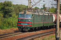
Public transport on electric traction appeared more than 130 years ago, today against the backdrop of environmental issues it has gained the widest distribution. Trams, trolleybuses, suburban trains and railway locomotives are equipped today with powerful electric motors. Electricity for their power supply is supplied from traction substations via a contact network. It is based on wires that make contact with the current collector in the process of current collection. Today there are contact network wires consisting of one or two wires. Double wires are used to improve the quality of current collection at a current strength of more than 1000A.
Features of the contact network wire
A number of requirements are imposed on the wires used in the creation of contact networks. The main ones among them are:
- high wear resistance;
- strength;
- high quality current collection;
- smooth contact surface;
- little windage.
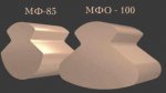 All these requirements are met, the abbreviation of which stands for "copper shaped". It got its name because of the original shape of the section, reminiscent of a figure eight. It was formed by the appearance of two gutters in the copper wire, used to securely fix the suspended reinforcement. receive such wires contact network by cold rolling copper wire. Where there are special requirements for the wear resistance of the wire, a bimetallic wire is used. It has a high strength steel core coated with a copper layer. To reduce the windage of the contact network, a wire with an oval cross section is used, which ensures a good quality of current collection.
Contact wires on the railway
The railway is today the main consumer of contact wire. The most commonly used wire with a cross section of 100, 120 and 150 sq. mm, it is used on hauls and main tracks of railway stations. On lines electrified with direct current, brand wire and is used. On AC lines, bimetallic cables twisted from bimetallic wires are used. Their advantage is high strength, wear resistance, corrosion resistance. Apply contact wire on the railway and with a cross section of 70 sq. mm, they complete the tracks on which shunting locomotives operate. Abroad, the variety of wires of contact networks of railways is even wider, the cross section of the wire used varies from 65 to 194 sq. mm.
The material for the contact wire is electrolytic copper; bronze is used in a number of countries. The bronze alloy with the addition of cadmium enhances the quality of the current collection, allows the use of higher voltages. Its wear resistance is twice as high as that of copper wire, but the high cost limits the scope of such a contact wire.
Trolleybus contact wires
The trolleybus contact network is the most complex, its feature is the presence of two wires. Each trolleybus contact pole has its own polarity, so they are carefully protected from possible convergence. In addition, the contact network is completed with arrows, systems for crossing different trolleybus lines. The wire has a classic shaped shape and is made from hard-drawn copper wire. On the main highways, a wire with a cross section of 85 sq. mm is used, for rarely used and emergency routes, a wire with a cross section of 65 sq. mm is used. It is allowed to use a bimetallic wire having a steel working surface.
Question:
Why do some electric trains (trains, trams, etc.) operate on DC, and some on a variable?
Answer:
The use of two types of current in the traction power supply system of railways has developed historically. The thing is that at the dawn of electrification, ERS used traction motors (TED) exclusively of direct current. This is due to their design features, the ability to regulate the speed and torque over a wide range by fairly simple means, the ability to work with overload, etc. Technically speaking, the electromechanical characteristics of DC motors are ideal for traction purposes.
AC motors (asynchronous, synchronous) have such characteristics that without special means of regulation their use for electric traction becomes impossible. There were no such means of regulation at the initial stage of electrification, and therefore, naturally, direct current was used in traction power supply systems at a voltage of first 1500 and then 3000 V, or, as electricians say, 1.5 or 3 kV. Traction substations were built, the purpose of which is to lower AC voltage supply network to the required value, and its rectification, i.e. conversion to constant.
But years passed, the volume of transportation by rail increased, and the load of traction networks grew accordingly. Power is equal to the product of current and voltage. The load grew, and the losses in the traction network also grew. After all, the losses are proportional to the square of the current, or. And this led to the need to strengthen the traction network, i.e. additional traction substations were built, the cross-section of wires increased. But all this did not radically solve the problem. There was only one way out - this is to reduce the magnitude of the current, but with the same load power, this can only be done by raising the magnitude of the voltage. And then a serious problem arose: for DC motors, a voltage of 3 kV turned out to be almost limiting. This is due to its design, the presence of a collector and brushes, a rotating armature winding. With an increase in voltage, the reliability of the operation of these nodes has significantly decreased. AC motors for traction at that time were completely unsuitable.
Thus, a contradiction arose - for the power supply system, the voltage of 3 kV turned out to be small, and for the TED it was impossible to increase it. But the way out was found by switching to alternating current! In the alternating current system, transformers began to be installed on the EPS, which, as you know, allow you to simply change the voltage value, are simple and reliable. After the transformer, a rectifier is installed, and then - a DC TED. At the same time, the voltage on the TED can be significantly reduced, thereby increasing their reliability, and the voltage of the traction network can be increased, reducing losses in it.
That is how it was done. The voltage of the AC traction network was increased to 25 kV, on the tires of the traction substation 27.5 kV. At the same time, the distance between traction substations increased, the cross section of the traction network wires decreased, and, consequently, the cost of the power supply system. At the initial stage of the introduction of alternating current, problems again arose. The fact is that the rectifying technique of that time was imperfect. Mercury rectifiers were used to rectify alternating current. And these are quite complex, expensive and capricious units, even when working in stationary conditions, not to mention their installation on EPS. This further delayed the introduction of alternating current.
With the advent of semiconductor rectifiers, this problem was also solved. While the alternating current system was being established, the direct current system was being rapidly introduced into the railway network. When all the problems with alternating current were solved, a significant part of the roads were already electrified with direct current. Thus, the AC electrification system is more advanced and is currently accepted as the main one. According to design standards, direct current should be used to complete the electrification of directions previously electrified on this current and to electrify sections adjacent to such directions. In addition, a 2×25 kV AC traction power supply system has now been developed. At the same time, the voltage of the supply network was increased to 50 kV, and the voltage in the contact network remained the same 25 kV. This system electrified the Baikal-Amur Mainline and a number of sections in the center of Russia. In places where DC and AC systems are joined, docking stations are arranged where AC and DC locomotives are changed. In addition, there are dual-power electric locomotives for AC and DC, but in our country they are of limited use. The development of semiconductor and microprocessor technology made it possible to remove restrictions on the use of AC motors on ERS. These motors, especially asynchronous ones, are simple and reliable.
Currently, electric locomotives and electric trains with AC motors have been produced, and further research is underway in this direction. And how do transitions from one current to another work at the boundary sections? via locomotives? No. The contact network at the docking station can switch to any kind of current - completely or in parts. At the same time, an electric locomotive, for example, of direct current, approaches the station, it is supplied to the COP with direct current, it drags the train onto a given path (if it is a passenger one, then to the platform), unhooks, goes to its parking lot (where there is only direct current), after which the current in the CS it switches to an alternating one, an alternating electric locomotive crawls out of its place and attaches itself to the abandoned train. There are also dual-system electric locomotives, which do not care what kind of current to drive. But they are quite expensive and there are few of them - cargo (and actually cargo-passenger) VL82 and VL82M in Vyborg and Mineralnye Vody and passenger EP10 (so far in a single copy) in Moscow-Kurskaya (works with train 061/062 Burevestnik Moscow - Nizhny Novgorod, but periodically leaves for the next test). A special design in Mineralnye Vody - although there is a branch electrified with direct current departing from the AC line, there are no switchable sections of the COP at the station. The main tracks are electrified with alternating current, and trains to Kislovodsk leave their tracks, where there is only direct current. Through trains from the main passage to Kislovodsk (there are few of them) run only under two-system electric locomotives; There are no direct current electric locomotives in the Mineralnye Vody.
Benefits of variable electric traction:
Reducing the current strength in the COP due to the use high voltage 25kV. The consequence is longer intervals between traction substations and a reduction in the number of substations themselves. Any required voltage on an electric locomotive and electric train can be obtained by a transformer, which has an efficiency close to 100% and very high reliability. (with direct current, for these purposes, electric machine converters (motor-generators) or electronic static converters are used, which are expensive and unreliable. On alternating current, much more power can be transmitted to an electric locomotive than on direct current. Hence the limitation of 200 km / h for high-speed AC trains can be used as backup power for signaling devices.At DC, in addition to the main VSLSSB, high-voltage transmission lines are also hung on the CS supports.On alternating current, it is easier to extinguish the electric arc that occurs during the passage of sectional insulators, during the breakdown of air gaps (lightning protection), when switching mast disconnectors, since the arc itself can go out when the phase passes through zero, and regardless of the presence in the circuit reactances. (On direct current, the presence of reactances only exacerbates the situation with arcing). The design of traction substations is simpler. It is easy to guess that one powerful rectifier is much more unreliable than a rectifier of an order of magnitude less power on each electric locomotive / motor car. There are other small benefits...
The electrification of railways in Russia (USSR) dates back to 1926, with the opening of the movement of suburban electric trains on the Baku-Sabunchi-Surakhani section with a length of 19 km. In Russia, the first electrified section Moscow-Mytishchi with a length of 17.7 km was put into operation in 1929.
Railway power supply devices must ensure: uninterrupted train traffic (with the required traffic sizes); reliable power supply various devices railway transport; power supply to all consumers of railway transport.
The rolling stock of electrified railways and the power supply system constitute a single electrical circuit. The power supply system of electrified roads includes devices that make up its external and traction parts.
The traction power supply system consists of traction substations and an electric traction network, the arrangement of which is determined by the electric traction system used.
Contact network current and voltage systems
Railways can be electrified by direct or alternating current system. However, in both cases, DC traction motors are used on the electric rolling stock. The traction system on three-phase alternating current has not gained popularity due to the fact that it leads to a limitation of the voltage in the network and speeds of movement due to the design features of the contact suspension. As a rule, a power supply system for electric rolling stock is used with single-phase alternating current, which is directly converted into direct current on the locomotives.
Traction substations on electrified DC roads perform two main functions: they lower the voltage of the supplied three-phase current and convert it to direct current. From the traction substations, electricity is fed through the supply lines to the contact network.
Traction substations are subdivided into substations of direct and alternating current. DC substations are placed at a distance of 15-20 km from one another, and alternating current - at a distance of 40-50 km, usually located in the area of the railway station.
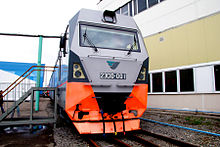
DC electric locomotive 2ES10 "Granit" with three-phase asynchronous traction motors.
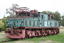
Industrial DC electric locomotive EL2 (1.5 kV), two upper pantographs and four side pantographs.
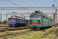
Electric locomotives different systems current at the docking station: on the left is a DC electric locomotive VL8 M, on the right is an AC electric locomotive VL80 T
Two-system electric locomotive VL82 m
Traction network
The traction network consists of contact and rail networks, supply and suction lines. contact network. On the main railways, electric power is supplied to the current collectors of electric locomotives and electric trains via an overhead contact network.
The contact network is a set of wires, structures and equipment that ensure the transmission of electrical energy from traction substations to current collectors of electric rolling stock.
The height of the contact wire suspension above the level of the top of the rail head must be at least 5750 mm at the hauls and railway stations of railway transport, and at least 6000 mm at railway crossings.
The distance from the axis of the extreme railway track to the inner edge of the contact network supports on the hauls and railway stations must be at least 3100 mm.
Supports in recesses must be installed outside the cuvettes.
In particularly heavily snow-covered recesses (except for rocky ones) and at their exits (over a length of 100 m), the distance from the axis of the extreme railway track to the inner edge of the contact network supports must be at least 5700 mm.
The list of such places is determined, respectively, by the owner of the infrastructure, the owner of non-public railway tracks.
On the existing lines before their reconstruction, as well as in especially difficult conditions on newly electrified lines, the distance from the axis of the railway track to the inner edge of the contact network supports is allowed at railway stations at least 2450 mm, and at stages - at least 2750 mm.
All specified dimensions are set for straight sections of the track. On curved sections, these distances should increase in accordance with the overall broadening established for the contact network supports.
All specified dimensions are set for straight sections of the track. On curved sections, these distances should increase in accordance with the overall broadening established for the contact network supports.
The contact network is made in the form of air suspensions. When the locomotive is moving, the current collector must not come off the contact wire, otherwise the current collection is disturbed and the wire may burn out. The reliable operation of the contact network largely depends on the sag of the wire and the pressure of the pantograph on the wire.
Types of contact suspensions. On railways, mainly chain contact suspensions are used: single, double and single with spring cables.
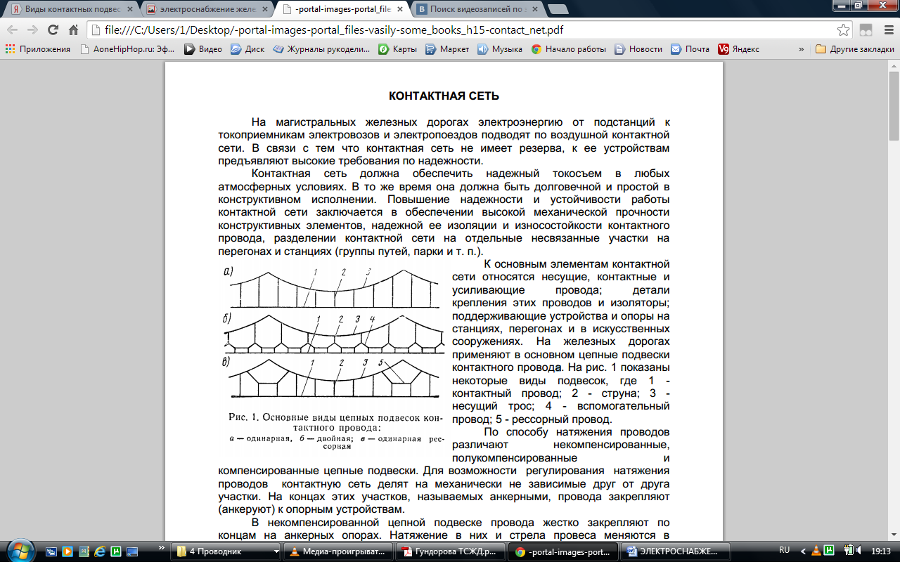
Rice. Chain contact hangers- single ( a), double ( b) and single with spring cables ( in): 1 - contact wire; 2 - string; 3 - carrying cable; 4 - auxiliary wire; 5 - spring cable
Rice. Chain suspension: 1 - support; 2 - thrust; 3 - console; 4 - insulator; 5 - carrying cable; 6 - contact wire; 7 - strings; 8 - latch; 9 - insulator
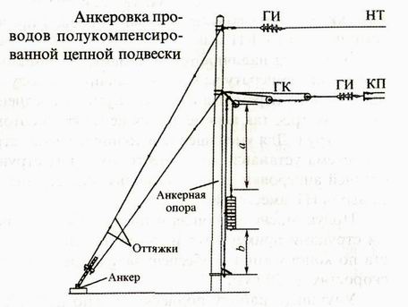
Wire tension method There are uncompensated, semi-compensated and compensated chain suspensions. To be able to regulate the tension of the wires, the contact network is divided into sections that are mechanically independent of each other. At the ends of these sections, called anchor, the wires are fixed (anchored) to the supporting devices. To reduce the sag during seasonal temperature changes, both ends of the contact wire (sometimes the carrier cable) are pulled to the anchor supports and cargo compensators are suspended from them through a system of blocks and insulators
AT uncompensated chain suspension wires are rigidly fixed at the ends on anchor supports. The tension in them and the sag vary depending on temperature, wind load and ice.
AT semi-compensated chain suspension with the help of compensator weights 5, the tension of the contact wire is automatically maintained when meteorological conditions change, and the carrier cable is fixed on supports 1 (Fig. 2, a). With such a suspension, the distance between the supports is usually 60-70 m. The use of spring suspension of the contact wire to the carrier cable at the supports with a semi-compensated suspension (Fig. 1, c) makes it possible to ensure reliable current collection for speeds up to 120 km / h. On the diagram of Fig. 2, b: 2 - guy; 3 - carrying cable; 4 - load fluctuation limiter; 6 - fixed roller; 7 - movable rollers; 8 - insulators.
At compensated chain suspension (see Fig. 2, b) in the contact wire 9 and the carrier cable is automatically maintained almost constant tension. Compensated suspension provides normal current collection at speeds up to 160 km/h and above.
Contact network sectioning devices. At the junction of hauls to the station and in some cases on hauls, insulating mates of anchor sections are used, which provide the so-called longitudinal sectioning of the contact network.
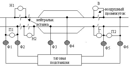
F1-F6 - feeder disconnectors.
H1, H2 - disconnectors of neutral inserts.
P1, P2 - transverse disconnectors.
C, D - longitudinal disconnectors.
When powering individual sections from different phases of alternating current, apply pairing of anchor sections with a neutral insert . Structurally, it consists of two air gaps arranged in series. The neutral insert is designed so that for any combination of raised current collectors of electric locomotives and electric trains, the possibility of simultaneous closing of both air gaps is excluded, i.e. connections of various sections of the contact network.
To separate the contact network stations on electrically independent sections use sectional insulators. Electrical connection or disconnection of individual sections of the contact suspension is carried out by longitudinal sectional disconnectors.
Docking sections of alternating and direct current. The docking of such sections is carried out on our railways in one of two ways. The first method is the sectioning of the contact network of the docking station with the switching of individual sections to power supply from DC or AC feeders, the second is the use of dual-powered electric rolling stock, i.e. An electric locomotive switches from direct current to alternating current and vice versa.
The contact network of docking stations has groups of isolated sections: direct current, alternating current and switchable. Switched sections are supplied with electricity through so-called grouping points. The contact network from one type of current to another is switched by special switches with motor drives installed at the grouping points. Each point has two AC supply lines and two DC supply lines from the AC/DC traction substation.
The current system and the magnitude of the voltage in the contact network
On the railway network, two electric traction systems are used: on direct current with voltage in the traction network 3 kV and on single-phase alternating current with voltage 25 kV standard frequency 50 Hz. Moreover, in both cases, only direct current traction motors are used on electric locomotives.
DC supply has a number of disadvantages: DC is very difficult to transform, i.e. increase or decrease the voltage without significant losses. The higher the power of the electric locomotive, the greater the loss; to prevent them, it is necessary to reduce the distance between traction substations and increase the cross section of the contact wire, but this will lead to copper consumption. At a voltage of 3 kV, traction substations are located on average every 20-25 km, and the consumption of copper per kilometer of the contact network reaches 10 tons. In addition, part of the traction current goes into the ground, forming "stray currents", which causes electrochemical corrosion. This reduces the service life of rails, reinforced concrete bridges, overpasses, etc.
The supply of alternating current is devoid of these shortcomings. To change its voltage, it is enough to have a conventional transformer, therefore, traction substations are simpler and cheaper. But an AC electric locomotive was created only in 1938; a mercury rectifier was used to convert AC to DC.
At present, electric locomotives with semiconductor rectifiers have been created. VL-60, VL-80k, BL-80T. The use of single-phase alternating current with a voltage of 25 kV made it possible to reduce the cross section of the contact wire by about half and increase the distance between substations to 40-60 km.
A further increase in the freight density of railways, an increase in the mass of trains would lead to an increase in voltage in the contact network and the creation of fundamentally new electric locomotives. This problem was solved by introducing a more economical 2 x 25 kV AC power supply system. With such a system, linear autotransformers are installed every 8-15 km. Electricity from traction substations to autotransformers is supplied with a voltage of 50 kV through a contact suspension and an additional supply wire. From autotransformers to electric locomotives, electricity is transmitted with a voltage of 25 kV. As a result, voltage losses become smaller, and the distance between adjacent substations can be increased up to 70-80 km.
A significant disadvantage of alternating current is the electromagnetic effect on metal structures along the tracks. As a result, they are directed dangerous voltage, and serious interference occurs in automation devices. Therefore, expensive protective structures have to be used.
Until 1955, the electrification of railways was carried out on direct current, and after 1955 - on alternating current. The transition from direct to alternating current ensured a reduction in the specific consumption of non-ferrous metals and the cost of maintaining traction substations. In the late 1970s a new 2x25 kV power supply system was introduced at the Vyazma - Orsha section, which stabilized the voltage levels of the contact network, significantly reduced the electromagnetic effect of electric traction on communication devices.